Eureka AIR delivers breakthrough ideas for toughest innovation challenges, trusted by R&D personnel around the world.

Tube stent delivery system

A tube support and tube wall technology, which is applied in the field of tube support distribution systems, can solve the problems of difficult to pull out the support, biting of the wire rope, damage to the tube support, etc., and achieve the effect of firm fitting

Active Publication Date: 2020-11-27
西卢克斯株式会社
View PDF13 Cites 0 Cited by
  • Summary
  • Abstract
  • Description
  • Claims
  • Application Information

AI Technical Summary

Problems solved by technology

As a result, the cord bites into the tube holder (damages the holder), making it difficult to pull out (release)

Method used


Image

  • Tube stent delivery system
  • Tube stent delivery system
  • Tube stent delivery system

Examples


other Embodiment approach

[0120] In the above-mentioned embodiment, the opening direction of the first fitting hole and the opening direction of the second fitting hole are not particularly limited, but when the inner catheter is pulled out from the pipe holder or the outer catheter, the bending of the tube holder or the outer catheter In some cases (when the pipe holder or the outer catheter is in a pre-bent shape), the opening direction of the first fitting hole and the opening direction of the second fitting hole may be opened in a direction other than the bending direction. A first fitting hole and a second fitting hole are formed.

[0121] For example, it can also be as Figure 14 As shown, the first fitting hole 43 is formed in a direction rotated by 180° around the axis of the pipe holder with respect to the bending direction X of the pipe holder 10 . also, Figure 14 yes figure 2 B-B sectional view shown.

[0122] Since the stent delivery system is configured in this way, when the inner ca...


PUM


Abstract

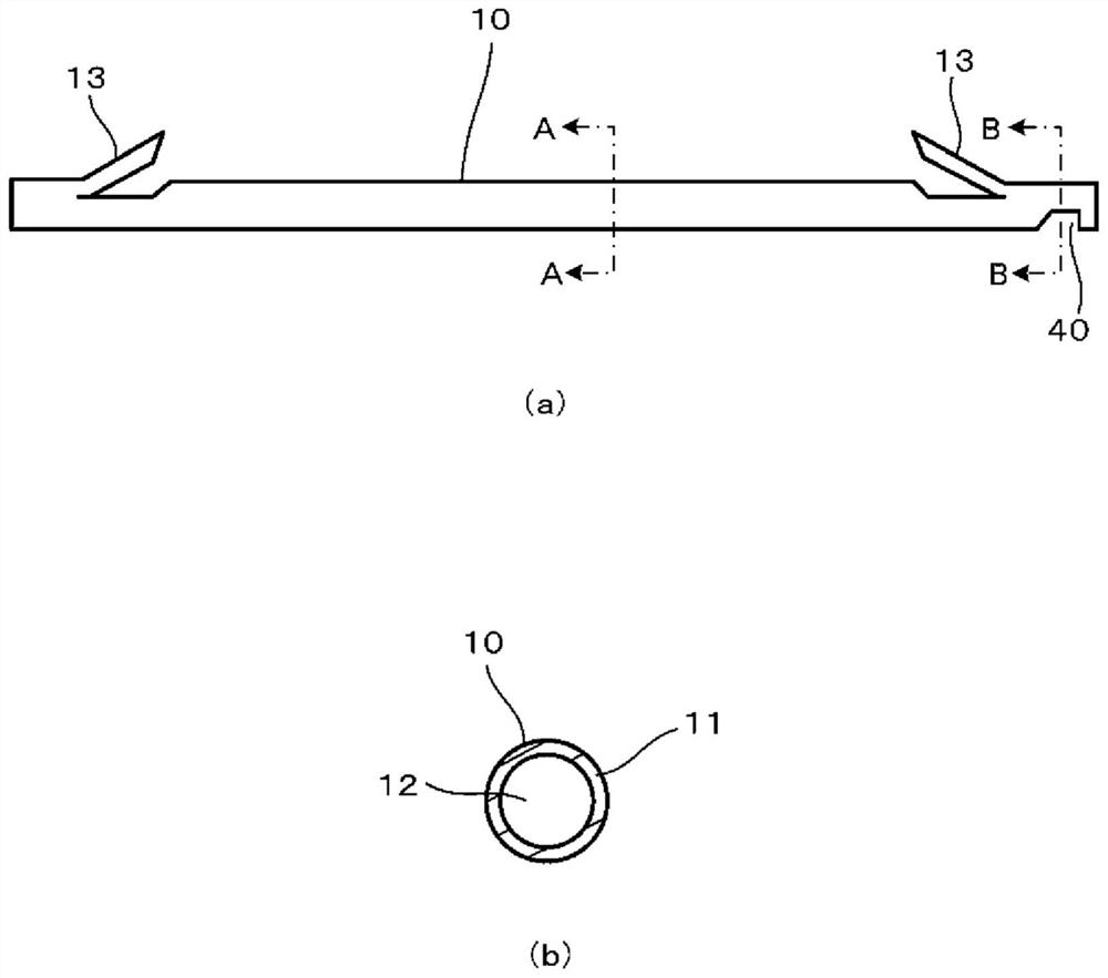
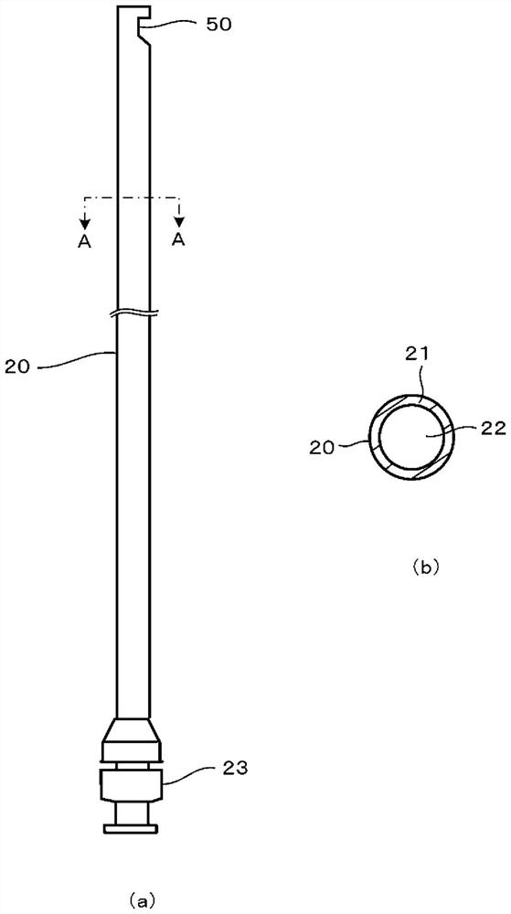
[Problem] To provide a tube stent delivery system which has a simple structure and whereby a tube stent is easily released. [Solution] A tube stent 10 has a ring-shaped first tube wall part 11, a hollow first insertion part 12 surrounded by the first tube wall part, and a first fitting part 40 for fitting with an outer catheter 20, the first fitting part being provided with a first fitting piece 42, a first fitting hole 43, and a first body 41. The outer catheter has a ring-shaped second tube wall part 21, a hollow second insertion part 22 surrounded by the second tube wall part, and a secondfitting part 50 for fitting with the tube stent, the second fitting part being provided with a second fitting piece 52, a second fitting hole 53, and a second body 51. The first fitting piece is inserted in the second fitting hole, and the second fitting piece is inserted in the first fitting hole, whereby the first fitting piece and the second fitting piece are fitted together, and the fitting ismaintained by insertion of an inner catheter in the first insertion part of the tube stent and the second insertion part of the outer catheter.

Description

technical field [0001] The present invention relates to a tube stent delivery system for drainage of bile duct or pancreatic duct, etc. Background technique [0002] Some tube stent delivery systems are known, which can pull the tube stent back when it is not accurately positioned at the target position after being delivered into the body (see Patent Document 1 and Patent Document 2). [0003] For example, there is a tube stent distribution system (hereinafter referred to as the existing tube stent delivery system), which connects the tube stent and the push catheter via a wire, and can release the connection between the tube stent and the push catheter by pulling the inner catheter. [0004] In addition, Patent Document 1 discloses a delivery system for a stent, wherein the push catheter has a hole for attaching a string-shaped body to the end, the stent has a hole for hooking and fixing, and the nub-shaped body is loosely fitted from the inside of the stent. The loose fit...

Claims


Application Information

Patent Timeline
IPC IPC(8): A61F2/95
CPCA61F2/95A61F2002/9505A61F2/94A61M27/002A61M2210/1075A61F2230/0013A61F2230/0019A61F2230/0026A61F2220/0016A61F2230/0023A61F2/962A61F2/97A61F2/9522A61F2002/9665A61F2002/041
Inventor 古桥伸一
Owner 西卢克斯株式会社
Why Eureka
Eureka Blog
Learn More