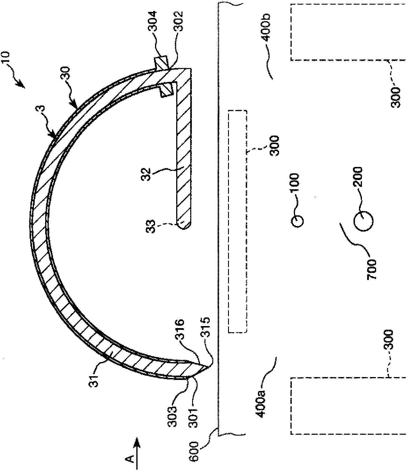
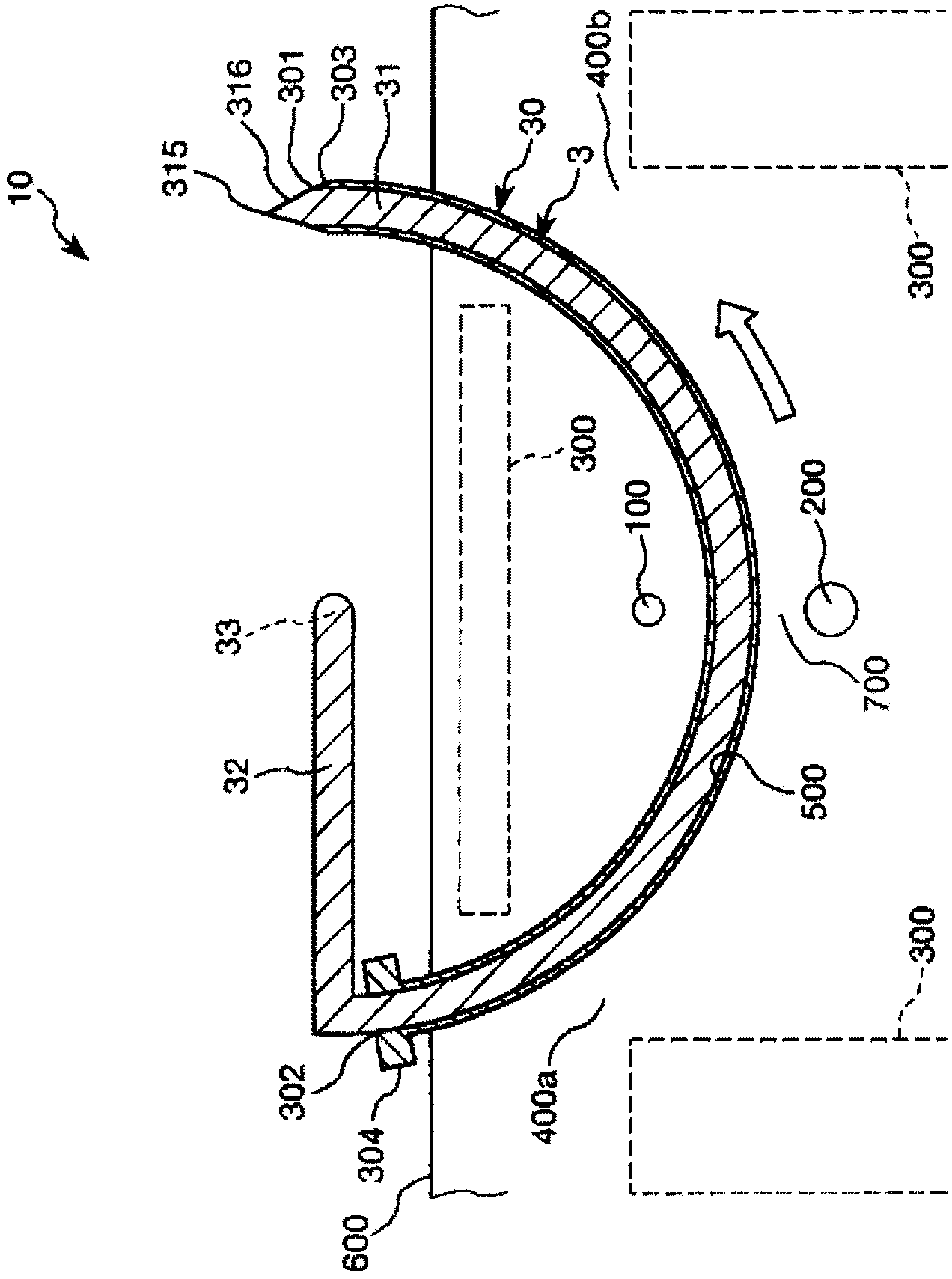
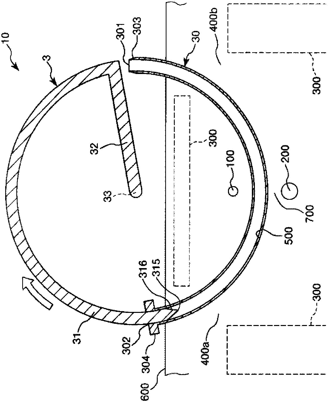
Medical tube and medical tube assembly
A medical tube and opening technology, applied in application, trocar, medical science, etc., can solve the problems of flattening of biological tissue and difficult insertion operation
- Summary
- Abstract
- Description
- Claims
- Application Information
AI Technical Summary
Problems solved by technology
Method used
Image
Examples
no. 1 approach >
[0055] Figure 1 to Figure 11 are respectively sectional views sequentially showing the usage method of the first embodiment of the medical tube (medical tube assembly) of the present invention, Figure 12 From figure 1 The figure (side view) observed in the direction of arrow A in Figure 13 yes Figure 7 The BB line sectional view in Figure 14 yes Figure 7 The sectional view of line C-C in Figure 15 From Figure 7 ((a) shows the state before the separation part is separated, and (b) shows the state after the separation part is separated). In addition, for the convenience of explanation below, the Figure 1 to Figure 12 in (for Figure 17 ~ Figure 19 Similarly) the upper side is referred to as "upper" or "upper", and the lower side is referred to as "lower" or "below". In addition, the needle tip side is called "tip end", and the opposite side is called "basal end".
[0056] Figure 7 ~ Figure 8 The illustrated medical tube assembly 1 includes a medical tube (tube...
no. 2 approach >
[0119] Figure 16 It is a cross-sectional view showing a second embodiment of the medical tube (medical tube assembly) of the present invention.
[0120] Hereinafter, a second embodiment of the medical tube and the medical tube assembly of the present invention will be described with reference to this figure, but differences from the above-mentioned embodiment will be mainly described, and description of the same items will be omitted.
[0121] This embodiment is the same as the first embodiment except that the number of cavities formed is different.
[0122] Such as Figure 16 As shown, in the medical tube 2A of this embodiment, in addition to the lumen 25 into which the implant 8 is inserted, a lumen 26 into which the guide wire 40 is inserted is also formed. The lumen 25 and the lumen 26 are formed independently of each other. This prevents the implant 8 from interfering with the guide wire 40, so that, for example, the guide wire 40 can be inserted and removed smoothly....
no. 3 approach >
[0125] Figure 17 ~ Figure 19 Each is a cross-sectional view sequentially showing the method of use of the third embodiment of the medical tube (medical tube assembly) of the present invention.
[0126] Hereinafter, a third embodiment of the medical tube and the medical tube assembly of the present invention will be described with reference to these drawings, but differences from the above-mentioned embodiment will be mainly described, and descriptions of the same items will be omitted.
[0127] This embodiment is the same as the first embodiment except that the separation part is omitted from the medical tube.
[0128] Such as Figure 17 , Figure 18 As shown, the medical tube 2B of the present embodiment omits the separating portion 235 that the medical tube 2 of the first embodiment has.
[0129] In addition, the distal end portion 81 of the implant 8 protrudes from the distal opening portion 21 of the medical tube 2B in advance.
[0130] As an example of the usage method...
PUM
 Abstract
Description
Claims
Application Information
 - R&D
- Intellectual Property
- Life Sciences
- Materials
- Tech Scout
- Unparalleled Data Quality
- Higher Quality Content
- 60% Fewer Hallucinations
Browse by: Latest US Patents, China's latest patents, Technical Efficacy Thesaurus, Application Domain, Technology Topic, Popular Technical Reports.
© 2025 PatSnap. All rights reserved.Legal|Privacy policy|Modern Slavery Act Transparency Statement|Sitemap|About US| Contact US: help@patsnap.com


