Cutting equipment for ceramic tile chamfering
A technology of cutting equipment and chamfering, applied in stone processing equipment, stone processing tools, work accessories, etc., can solve the problems of low efficiency and high risk factor of operation, achieve the effect of reducing work intensity, improving safety factor, and facilitating subsequent cleaning
- Summary
- Abstract
- Description
- Claims
- Application Information
AI Technical Summary
Problems solved by technology
Method used
Image

Examples
Embodiment 1
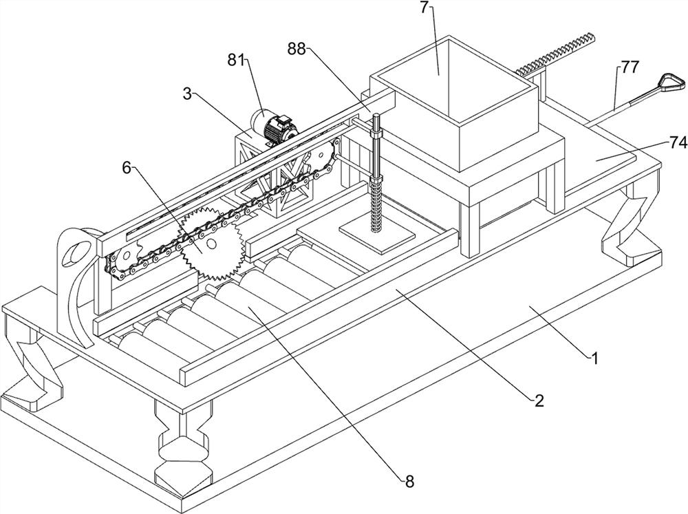
[0025] A cutting device for chamfering tiles, such as Figure 1-4 As shown, it includes a bottom plate 1, a frame 2, a placement frame 3, a placement block 4, a small motor 5, a cutting wheel 6, a pusher assembly 7 and a chamfering assembly 8. The top of the bottom plate 1 is connected with a frame 2, and the frame 2 The rear side of the top is connected with a placement frame 3 and a placement block 4, the placement frame 3 is located on the right side of the placement block 4, a small motor 5 is installed on the placement block 4, a cutting wheel 6 is connected to the small motor 5, and the top right side of the frame 2 is installed Pushing material assembly 7 is arranged, and chamfering assembly 8 is installed on the left side of frame 2 tops.
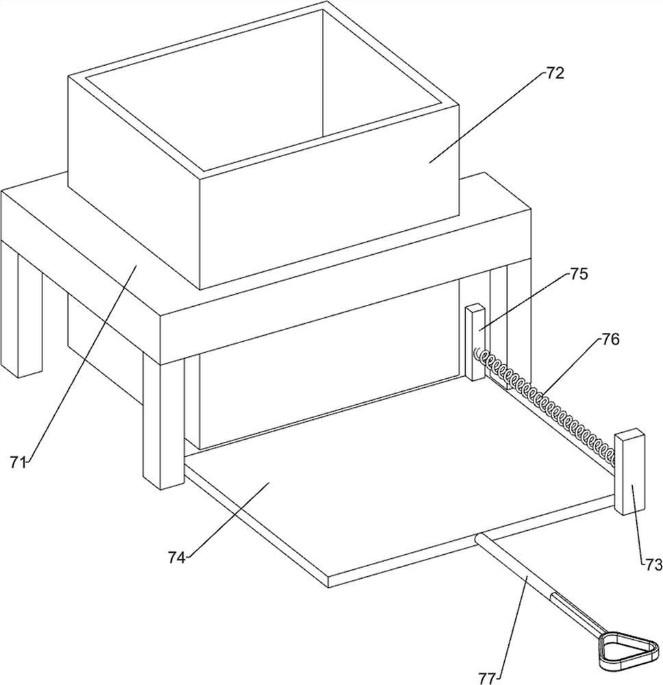
[0026] The pushing assembly 7 includes a fixed mount 71, a bucket 72, a fixed block 73, a push plate 74, a connecting block 75, a back-moving spring 76 and a push rod 77, and the right side of the frame 2 top is connected with a fix...
Embodiment 2
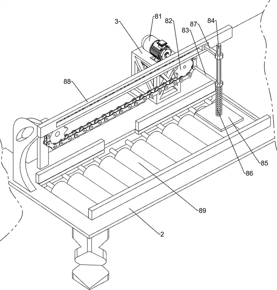
[0030] On the basis of Example 1, such as Figure 5 As shown, a linkage assembly 9 is also included, and the linkage assembly 9 includes a first guide plate 91, a first rack 92, a gear 93, a second guide plate 94, a second rack 95 and a dial 96, and the top of the fixed block 73 is connected with The first guide plate 91, the top of the first guide plate 91 is slidingly connected with the first rack 92, the bottom of the first rack 92 is connected with the connecting block 75, the rear side of the bucket 72 is connected with the gear 93 in a rotational manner, the first tooth The bar 92 is meshed with the gear 93. The rear side of the bucket 72 is connected with a second guide plate 94. The second guide plate 94 is located above the gear 93. The bottom of the second guide plate 94 is slidably connected with a second rack 95. The second rack 95 Engaged with the gear 93, the rear side of the chain of the chain transmission group 82 is connected with a shifting block 96, and the ...
Embodiment 3
[0033] On the basis of Example 2, such as figure 2 As shown, a material guide plate 10 and a material collection frame 11 are also included. The material guide plate 10 and the material collection frame 11 are connected to the rear side of the bottom plate 1 top, and the material guide plate 10 is located at the front side of the material collection frame 11 .
[0034] The waste generated in the process of chamfering and cutting can be collected through the through hole of the frame 2 and collected into the collecting frame 11 from the material guide plate 10, so that it is not necessary to manually collect and clean the generated waste, which is convenient for workers to follow up. clean up.
PUM
 Abstract
Description
Claims
Application Information
 - R&D
- Intellectual Property
- Life Sciences
- Materials
- Tech Scout
- Unparalleled Data Quality
- Higher Quality Content
- 60% Fewer Hallucinations
Browse by: Latest US Patents, China's latest patents, Technical Efficacy Thesaurus, Application Domain, Technology Topic, Popular Technical Reports.
© 2025 PatSnap. All rights reserved.Legal|Privacy policy|Modern Slavery Act Transparency Statement|Sitemap|About US| Contact US: help@patsnap.com