Signal laser emitter of unmanned aerial vehicle

A technology for laser transmitters and drones, applied in the field of laser transmitters, can solve the problems of high resistance of drones, easy generation of heat by internal components, inconvenient installation, etc., and achieve the effect of good adaptability and practicability

Active Publication Date: 2020-12-01
NANJING KAITIANYAN UAV TECH CO LTD
View PDF5 Cites 0 Cited by
  • Summary
  • Abstract
  • Description
  • Claims
  • Application Information

AI Technical Summary

Problems solved by technology

The use of UAVs is still relatively extensive. Whether in the military field or the civilian field, UAVs have played an important role. Taking the civilian field as an example, UAV oil aerial photography, agricultural plant protection, power inspection, forest fire prevention , high-altitude fire extinguishing, emergency communications, and UAV logistics and other applications. With the update of technology, the functions and applications of UAVs have gradually been expanded. Domestic companies are also actively expanding industry applications and developing UAVs. Technology, by installing a laser transmitter on the drone, it can be used for route guidance, information transmission, etc., to expand the overall function by installing components, so that it plays an important role in pre-emptive rescue and unmanned driving. However, due to the large overall volume of the existing laser transmitters, the resistance of the UAV during the movement is relatively large, and the overall size of the UAV is also different, which is not easy to install, and the accumulation of many internal components is easy to generate heat. and other problems, using reasonable technical solutions to these problems can solve the above problems, and has good practical effect

Method used


Image

  • Signal laser emitter of unmanned aerial vehicle
  • Signal laser emitter of unmanned aerial vehicle
  • Signal laser emitter of unmanned aerial vehicle

Examples


Embodiment Construction

[0027] The present invention will be described in further detail below in conjunction with the accompanying drawings.

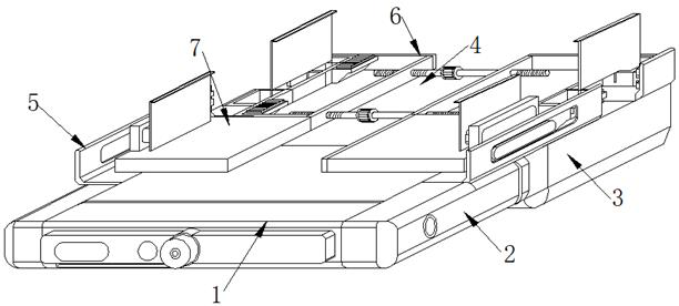
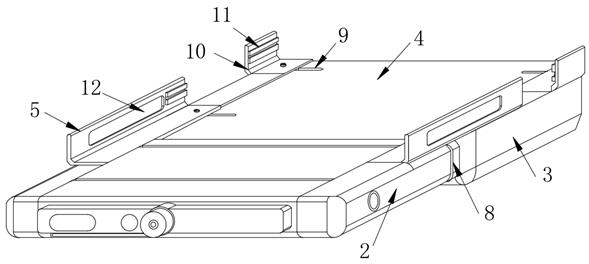
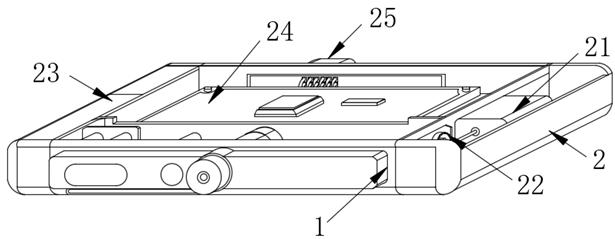
[0028] see Figure 1-8 , in the embodiment of the present invention, a UAV signal laser transmitter includes a flipping end 1, the rear end of the flipping end 1 is provided with a transmitting end shell 2, and the rear end of the transmitting end shell 2 is provided with a power supply end shell 3 , the upper surface of the power supply end shell 3 is provided with a fixed plate 4, a fixed frame 6 is arranged above the fixed plate 4, the front end of the fixed frame 6 is connected with an engaging end plate 7, and the left and right ends of the engaging end plate 7 are provided There are side-fixed groove plates 5.

[0029]Specifically, a mounting groove 8 is provided on the outer side of the rear end of the transmitting end shell 2, and the mounting groove 8 and the fixing plate 4 are connected by welding, and the mounting groove 8 and the transmitting end...


PUM


Abstract

The invention discloses a signal laser transmitter of an unmanned aerial vehicle. The invention relates to the technical field of laser transmitters. According to the technical scheme, the signal laser transmitter is characterized by comprising an overturning end; a transmitting end shell is arranged at the rear end of the overturning end; a power supply end shell is arranged at the rear end of the transmitting end shell; a fixed frame is arranged above the fixed plate; the front end of the fixed frame is connected with a clamping end plate; and side fixing groove plates are arranged at the left end and the right end of the clamping end plate correspondingly. Expansion slots are formed in the left side and the right side of the fixed frame; the expansion slots are formed in the fixed frame, a communication structure is formed between the expansion slots and the fixed frame, a contact block is fixed to the inner side face of the fixed frame, the contact block is connected with the fixedframe in a welded mode, and an attaching rubber pad is arranged on the upper surface of the contact block and embedded in the upper surface of the contact block. The structure can reduce resistance formed by the extra size in the moving process of the unmanned aerial vehicle; meanwhile, air filling ventilation is conducted on the internal structure, and the temperature of the heating assembly isfurther reduced.

Description

technical field [0001] The present invention relates to the technical field of laser emitters, and more specifically, relates to a UAV signal laser emitter. Background technique [0002] Unmanned aircraft is referred to as "UAV" for short, and the English abbreviation is "UAV". . The use of UAVs is still relatively extensive. Whether in the military field or the civilian field, UAVs have played an important role. Taking the civilian field as an example, UAV oil aerial photography, agricultural plant protection, power inspection, forest fire prevention , high-altitude fire extinguishing, emergency communications, and UAV logistics and other applications. With the update of technology, the functions and applications of UAVs have gradually been expanded. Domestic companies are also actively expanding industry applications and developing UAVs. Technology, by installing a laser transmitter on the drone, it can be used for route guidance, information transmission, etc., to expan...

Claims


Application Information

Patent Timeline
Patent Type & Authority Applications(China)
IPC IPC(8): B64D47/00
CPCB64D47/00B64U2101/00
Inventor 陈冲石晓雨曹军
Owner NANJING KAITIANYAN UAV TECH CO LTD
Why Eureka
Try Eureka