
A method of deploying a two-dimensional planar deployable mechanism on-orbit using satellite spin

A two-dimensional plane and satellite technology, applied to artificial satellites, motor vehicles, space navigation equipment, etc., can solve problems such as reverse voltage breakdown of electronic devices, mechanism damage, and large SADA reversal angular velocity of solar wings, etc., to achieve reduction Stiffness and deployment in place impact, slow impact, improve the effect of science

Active Publication Date: 2021-12-07
CHINA ACADEMY OF SPACE TECHNOLOGY
View PDF0 Cites 0 Cited by
  • Summary
  • Abstract
  • Description
  • Claims
  • Application Information

AI Technical Summary

Problems solved by technology

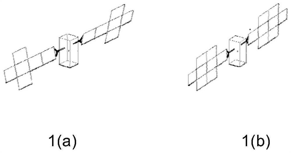
When the single side of the solar wing is increased from six panels to eight panels, the traditional method of deploying the middle panels to trigger the deployment of the side panels of the solar wing will still be used, which will cause the SADA rotation angle speed of the solar wing to be too large, which may cause mechanical damage or electronic failure. Device reverse voltage breakdown problem

Method used


Image

  • A method of deploying a two-dimensional planar deployable mechanism on-orbit using satellite spin
  • A method of deploying a two-dimensional planar deployable mechanism on-orbit using satellite spin
  • A method of deploying a two-dimensional planar deployable mechanism on-orbit using satellite spin

Examples


Embodiment Construction

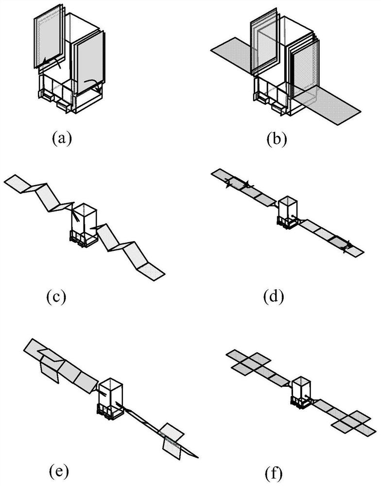
[0040] Attached below Figure 4 To further illustrate some details in the technical solution of the present invention, its implementation includes the following steps:

[0041] Step 1. Establishing a flexible multi-body dynamics model of satellite deployment on orbit with a two-dimensional expandable structure;

[0042]Step 2. Obtain the mass inertia characteristics of the satellite with a two-dimensional deployable structure, the hinge driving moment, friction moment, damper temperature and damping relationship data of the two-dimensional deployable structure, the maximum bearable force and moment of each hinge and weak structure, and the satellite Gyro maximum angular velocity measurement range;

[0043] Step 3. The satellite triaxial angular velocity is from ω min Start, multiply by 2 each time until ω max , calculate the satellite three-axis angular velocity data list, generally ω min Take 0.25deg / sec, ω max Take 64deg / sec;

[0044] Step 4: Determine the satellite co...


PUM


Abstract

The invention discloses a method for deploying a two-dimensional planar expandable structure on-orbit using satellite spin, the steps of which are as follows: 1) establishing a flexible multi-body dynamics model of a satellite with a two-dimensional expandable structure on-orbit; 2) acquiring a two-dimensional expandable structure The mass inertia characteristics of deployable structure satellites, the hinge driving torque, friction torque, damper temperature and damping relationship data of two-dimensional deployable structures, the maximum bearable force and moment of each hinge and weak structure, and the maximum angular velocity measurement range of satellite gyro;3 ) Calculate and obtain the satellite three-axis angular velocity data list; 4) Determine the satellite coordinate axes that can assist the deployment of the two-dimensional planar deployable structure; 5) Determine the satellite angular velocity that can assist the deployment of the spaceborne deployable structure through flexible multi-body dynamics analysis; 6 ) The satellite adjusts its attitude, and makes the satellite obtain the satellite spin angular velocity in step 5, and releases the deployable structure of the satellite to expand the constraining device.

Description

technical field [0001] The invention relates to a method for deploying a two-dimensional planar deployable structure by using satellite spin angular velocity, which can be used as a low-impact and highly reliable deploying method for spacecraft with a two-dimensional planar deployable structure such as large-scale high-power communication satellites and space-based radars. Background technique [0002] Large-scale and super-large communication satellites and space-based radar systems generally use large-scale solar wings as energy devices to meet their high power requirements, providing the required power for the entire star platform and loads; space-based radar systems use large-area planar expandable structures as Phased array antenna support structure to provide the required gain. Large-scale deployable solar wings are a typical large-scale planar deployable structure. With the continuous improvement of the output power of satellites to solar wings, the traditional in-lin...

Claims


Application Information

Patent Timeline
Patent Type & Authority Patents(China)
IPC IPC(8): B64G1/10B64G1/22B64G1/44
CPCB64G1/1007B64G1/222B64G1/44
Inventor 董富祥孙治国邹爽
Owner CHINA ACADEMY OF SPACE TECHNOLOGY
Learn More