Supercharge Your Innovation With Domain-Expert AI Agents!

Counter-rotating fan structure

A counter-rotating and fan technology, applied in the direction of non-volume pumps, non-variable pumps, electrical equipment structural parts, etc., can solve problems such as poor structural configuration design, influence of fan air outlet efficiency, and negative effects , to achieve the effect of improving characteristic performance, enhancing characteristic performance, and enhancing heat dissipation

Active Publication Date: 2020-12-01
DELTA ELECTRONICS INC
View PDF5 Cites 0 Cited by
  • Summary
  • Abstract
  • Description
  • Claims
  • Application Information

AI Technical Summary

Problems solved by technology

[0004] However, when the two fans are connected in series but the structural design is not good, it is very likely that the air output efficiency of the two fans will affect each other and interfere with each other.
In other words, connecting another fan in series not only has no bonus effect, but may lead to negative effects

Method used


Image

  • Counter-rotating fan structure
  • Counter-rotating fan structure
  • Counter-rotating fan structure

Examples


Embodiment Construction

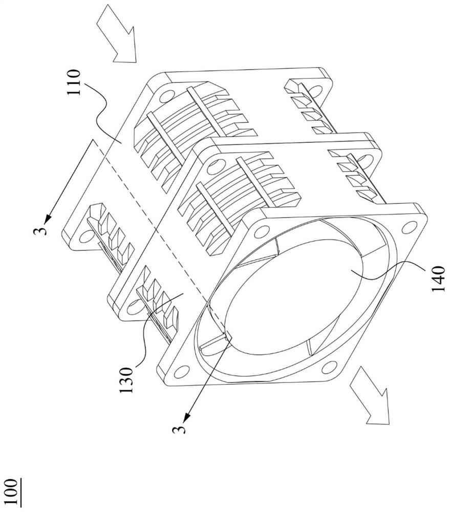
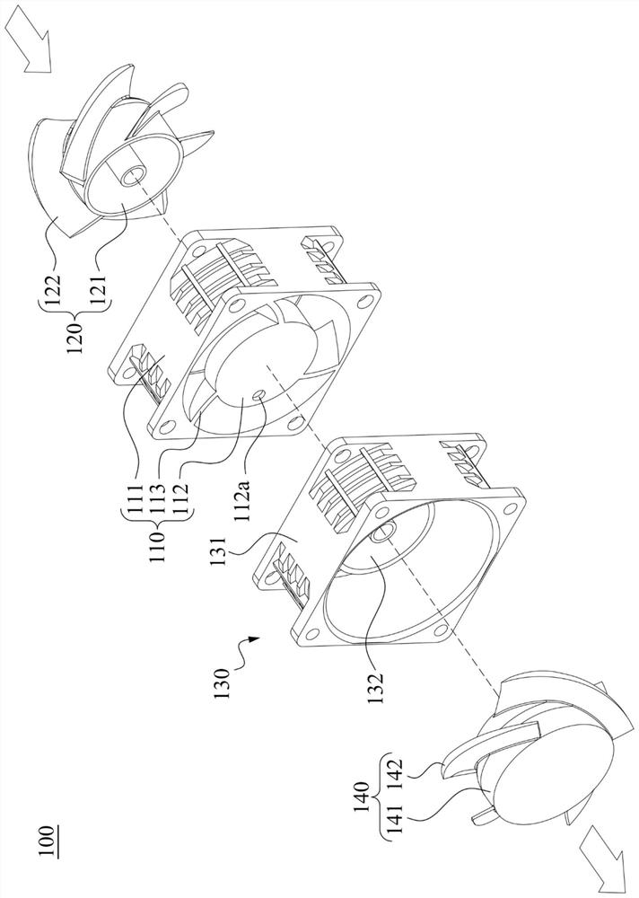
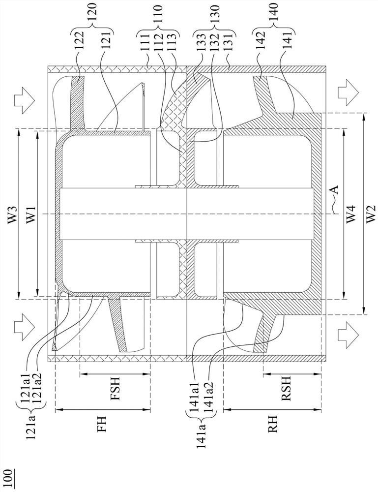
[0058] Please refer to Figure 1 to 3 . figure 1 To draw a stereo combination diagram of the swirl fan structure 100 according to an embodiment of the present invention. figure 2 To draw figure 1 The stereoscopic explosive diagram of the spin type fan structure 100. image 3 To draw figure 1 A cross-sectional view of the inverse fan structure 100 along the line segment 3-3. Figure 1 to 3 The direction of arrows represented is to indicate the direction of the spin fan. like figure 1 and figure 2 As shown in the present embodiment, the swirl fan structure 100 includes a first housing 110, a first fan 120, a second housing 130, and a second fan 140. The connection relationship between the components contained in the rotary fan structure 100 will be described in detail below.

[0059] like figure 2 As shown in the present embodiment, the first housing 110 includes a first outer wall 111, a first base 112, and a plurality of first calibration blades 113. The first outer wall 111 has a ho...


PUM


Abstract

The invention discloses a contra-rotating fan structure. The structure comprises a first base, a first fan, a second base and a second fan. The first fan is rotatably arranged on the first base and comprises a first hub. The first hub has a first maximum width. The second fan is rotatably arranged on the second base and comprises a second hub. The second hub has a second maximum width. The first base and the second base are located between the first fan and the second fan. The second maximum width is greater than the first maximum width.

Description

Technical field [0001] The present invention relates to a fan structure, in particular, for a swirl fan structure. Background technique [0002] With the rapid development of electronics toward high performance, high frequency, high speed and thinness, electronic products are getting higher and higher, and thus it is easy to generate unstable phenomena, affecting product reliability. Therefore, heat dissipation has become one of the important topics of current electronics development. [0003] Today, the heat sink is used as a common design in the electronic product, but for electronics producing a large amount of thermal energy, a single fan is not enough to effectively dissipate heat, and to avoid a single fan due to failure, the heat dissipation device is interrupted. Therefore, it is generally used to use a plurality of fans at the same time to reach the air volume of the airflow. Wherein, the plurality of fans are a axial fan. [0004] However, when the two-fan, the two-wind...

Claims


Application Information

Patent Timeline
Patent Type & Authority Applications(China)
IPC IPC(8): F04D25/16F04D29/32F04D29/54H05K7/20
CPCF04D25/166F04D29/329F04D29/541H05K7/20136F04D19/007F04D29/646F04D19/024F04D29/542
Inventor 陈建宏杨朝富黄建智黄躍龙张楯成
Owner DELTA ELECTRONICS INC
Features
  • R&D
  • Intellectual Property
  • Life Sciences
  • Materials
  • Tech Scout
  • Unparalleled Data Quality
  • Higher Quality Content
  • 60% Fewer Hallucinations
Learn More