
Wind wheel heat dissipation type LED environment decoration lamp

An LED light board, heat dissipation technology, applied in the cooling/heating device, lighting device, fixed lighting device and other directions of lighting devices, can solve the problems of poor decorative effect and high temperature, and achieve the effect of colorful decorative effects

Inactive Publication Date: 2020-12-01
黄奎奎
View PDF0 Cites 0 Cited by
  • Summary
  • Abstract
  • Description
  • Claims
  • Application Information

AI Technical Summary

Problems solved by technology

[0005] The purpose of the present invention is to solve the above-mentioned problems of poor decorative effect and high temperature, to provide a wind wheel heat dissipation LED environmental decorative lamp with good decorative effect and good heat dissipation function

Method used


Image

  • Wind wheel heat dissipation type LED environment decoration lamp
  • Wind wheel heat dissipation type LED environment decoration lamp
  • Wind wheel heat dissipation type LED environment decoration lamp

Examples


Embodiment 1

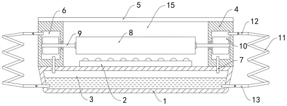
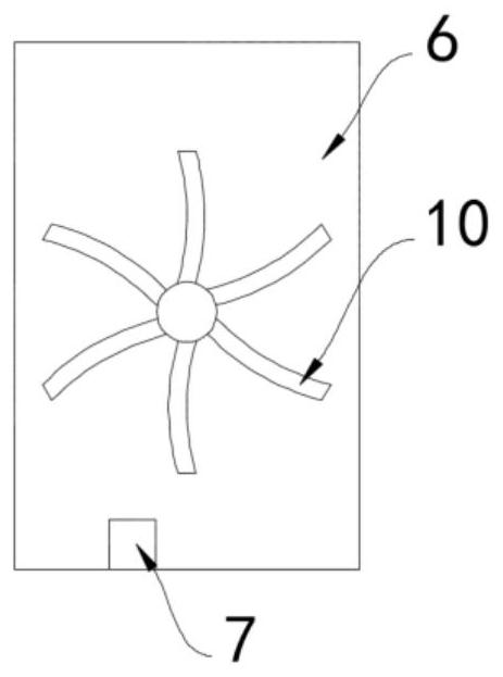
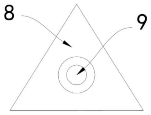
[0020] Such as Figure 1-3 As shown, a wind wheel heat dissipation LED environmental decorative lamp includes a base 1 and an LED lamp board 2 installed on the upper surface of the base 1. The base 1 is provided with a cooling cavity 3, and the cooling cavity 3 is filled with cooling liquid. It is dichloromethane with a boiling point of 40°C. The upper surface of the base 1 is fixedly connected with an annular enclosure 4. The upper end of the annular enclosure 4 is equipped with a light-transmitting plate 5 parallel to the base 1. There are two ring enclosures inside the annular enclosure 4. An evaporation chamber 6, the evaporation chamber 6 communicates with the cooling chamber 3 through the connecting pipe 7, and the top of the LED lamp board 2 is provided with a triangular prism 8, and the two ends of the triangular prism 8 are rotatably connected with the inner side wall of the annular enclosure 4 through the rotating shaft 9.

[0021] The end of the rotating shaft 9 awa...

Embodiment 2

[0025] Such as Figure 4-5 As shown, the difference between this embodiment and Embodiment 1 is that: the rotating shaft 9 is fixedly sleeved with a ring magnet 14, the ring magnet 14 is composed of two semi-ring magnets with opposite magnetic fields, and a flexible magnet is provided under the transparent plate 5. Transparent plate 15, the flexible transparent plate 15 is fixedly connected with the inner ring side wall of the annular enclosure 4, and the space between the flexible transparent plate 15 and the light-transmitting plate 5 is filled with refraction liquid, the refraction liquid is water, and the lower surface of the flexible transparent plate 15 is fixed Two permanent magnet blocks 16 matching the ring magnet 14 are connected.

[0026] In the present embodiment, during the rotation process of the rotating shaft 9 driven by the wind impeller 10, the ring magnet 14 rotates synchronously, and then the semi-ring magnets of two sections of magnetism opposite in the ri...


PUM


Abstract

The invention belongs to the field of LED lamps, and in particular relates to a wind wheel heat dissipation type LED environment decoration lamp. The lamp comprises a base and an LED lamp panel installed on the upper surface of the base, a cooling cavity is formed in the base, cooling liquid is contained in the cooling cavity, the upper surface of the base is fixedly connected with an annular fence, A light-transmitting plate parallel to the base is installed at the upper end of the annular fence, two evaporation cavities are formed in the annular fence and communicated with the cooling cavitythrough communicating pipes, a prism is arranged above the LED lamp panel, and two ends of the prism are rotationally connected with the inner side wall of the annular fence through rotating shafts.The cooling liquid evaporates and absorbs heat, a good cooling and heat dissipation effect is achieved, a fan blade wheel can be impacted to drive the prism to rotate, the refraction angle of variousmonochromatic light refracted by lamplight is changed, continuously-swaying light and shadow are formed, and a more colorful decoration effect is achieved.

Description

technical field [0001] The invention belongs to the field of LED lamps, and in particular relates to a wind wheel heat dissipation type LED environmental decoration lamp. Background technique [0002] With the improvement of people's requirements for environmental decoration, the role of lighting in the architectural environment is increasing day by day. Lighting design has become an important part of architectural design. Among them, LED environmental decorative lights are widely used to meet people's requirements for beautiful environment, suitable brightness, There are multiple levels of requirements such as comfortable layered space and rich three-dimensional sense. [0003] The visual effect of traditional LED environmental decoration lights is single and does not have a dynamic decorative effect. In order to achieve a good performance effect, a high-power lighting source is often used, resulting in a high internal temperature. The LED light source works in a high-tempe...

Claims


Application Information

Patent Timeline
IPC IPC(8): F21S8/00F21V29/51F21V5/02F21V5/00F21V14/06F21Y115/10
CPCF21S8/00F21V5/00F21V5/02F21V14/06F21V29/51F21Y2115/10
Inventor 黄奎奎陈会会
Owner 黄奎奎
Learn More