Steam and liquid return protection device

A protection device and liquid collecting pipe technology, which is applied in the direction of refrigeration and liquefaction, drying solid materials, and drying solid materials without heating. Effects of hitting damage, shortening cooling time, and reducing cost

Pending Publication Date: 2020-12-01
上海共和真空技术有限公司
View PDF0 Cites 0 Cited by
  • Summary
  • Abstract
  • Description
  • Claims
  • Application Information

AI Technical Summary

Problems solved by technology

[0002] At present, in the refrigeration system of refrigerated vacuum dryers produced by domestic and foreign manufacturers, when the return air end is low temperature, in order to prevent the compressor from liquid hammering, a vapor-liquid separator device is added to the return air pipeline of the compressor; , only through the compressor solenoid valve pulse mode, the refrigeration system is operated; this structure of the refrigeration return steam system has several major disadvantages: 1. Although there is a vapor-liquid separator device, the refrigeration oil cannot be vaporized, so the compressor cannot be completely avoided. 2. Because of the increased buffer, it is more difficult to identify the opening size of the expansion valve, which is not intuitive, and increases the hidden danger of hydraulic shock of the press; 3. Increases the cost of the vapor-liquid device; 4. Freezing In the SIP sterilization and cooling stage of the drying machine, the temperature of the pipeline is high, and the compressor needs to be refrigerated by means of electromagnetic valve pulses, and the cooling cycle is long; Abnormal sound, the press is easily damaged

Method used


Image

  • Steam and liquid return protection device

Examples


Embodiment Construction

[0024] The present invention will be further described below in conjunction with the accompanying drawings.

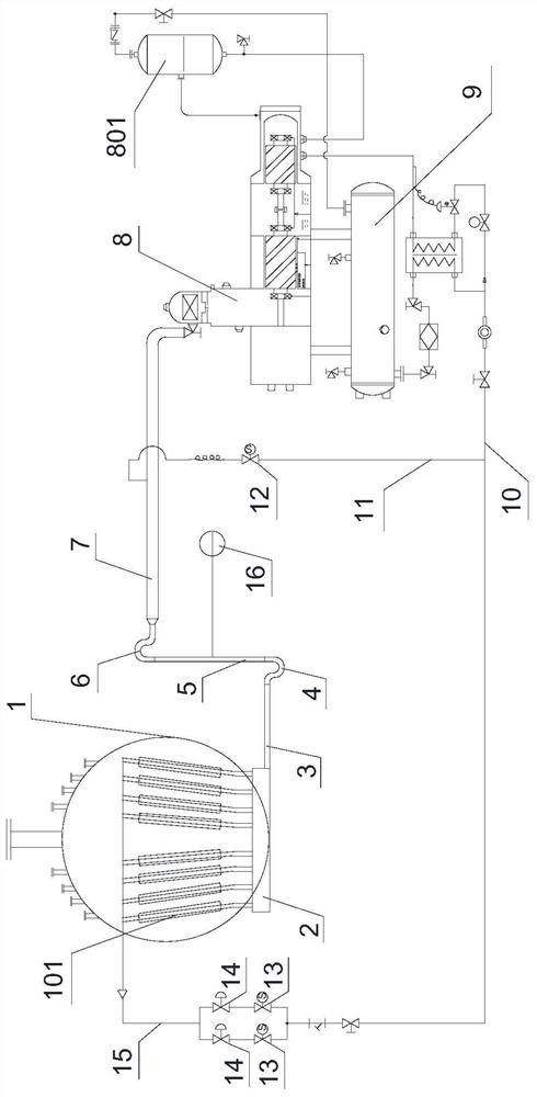
[0025] see figure 1 , the figure shows the vapor return and liquid return protection device of the present invention, the vapor return and liquid return protection device is externally placed on the condenser coil 101 of the condenser 1 of a freeze dryer refrigeration system (not shown in the figure), the return The vapor return protection device includes:

[0026] A liquid collecting pipe buffer 2, the inlet end of the liquid collecting pipe buffer 2 is connected with the outlet end of the condensing coil 101;

[0027] A horizontal pipe 3, the inlet end of the horizontal pipe 3 is connected with the outlet end of the liquid collecting pipe buffer 2;

[0028] A first U-bend 4, the inlet end of the first U-bend 4 is connected to the outlet end of the horizontal pipe 3;

[0029] A vertical pipe 5, the inlet end of the vertical pipe 5 is connected with the outlet end o...


PUM


Abstract

The invention discloses a steam and liquid return protection device externally arranged on a condensing coil pipe of a condenser of a refrigeration system of a freeze dryer. The steam and liquid return protection device comprises a liquid collecting pipe buffer, a horizontal pipe, a first U-shaped bent pipe, a vertical pipe, a second U-shaped bent pipe, a return steam buffer pipe, a compressor, awater condenser, a liquid outlet pipe, a capillary pipe, a return steam cooling control valve, two cooling valves connected to the outlet end of the liquid outlet pipe in parallel, two expansion valves and a liquid conveying pipe. The liquid collecting pipe buffer and the return steam buffer pipe are additionally arranged at the outlet end of the condensing coil pipe, so that the compressor is prevented from being damaged by liquid impact; and meanwhile, the return steam cooling control valve and the capillary pipe are additionally arranged, the return steam buffer pipe is cooled under the condition of high return steam temperature, the cooling time is shortened, and the cost is reduced.

Description

technical field [0001] The invention relates to a vapor return and liquid return protection device. Background technique [0002] At present, in the refrigeration system of refrigerated vacuum dryers produced by domestic and foreign manufacturers, when the return air end is low temperature, in order to prevent the compressor from liquid shock, a vapor-liquid separator device is added to the return air pipeline of the compressor; , only through the compressor electromagnetic valve pulse mode, the refrigeration system is operated; this structure of the refrigeration return steam system has several major disadvantages: 1. Although there is a vapor-liquid separator device, the refrigeration oil cannot be vaporized, so the compressor cannot be completely avoided. 2. Because of the increased buffer, it is more difficult to identify the opening size of the expansion valve, which is not intuitive, and increases the hidden danger of hydraulic shock of the press; 3. Increases the cost...

Claims


Application Information

Patent Timeline
IPC IPC(8): F25B43/02F25B41/06F26B5/06
CPCF25B43/02F26B5/06
Inventor 胡治国
Owner 上海共和真空技术有限公司
Why Eureka
Try Eureka