Heat pump system with ejector

A heat pump system and ejector technology, which can be applied to compressors with reversible cycles, lighting and heating equipment, fluid circulation arrangements, etc. , to achieve the effect of improving equipment reliability, extending system life, and stable pressure changes

Inactive Publication Date: 2020-06-05
李社红
View PDF0 Cites 2 Cited by
  • Summary
  • Abstract
  • Description
  • Claims
  • Application Information

AI Technical Summary

Problems solved by technology

[0002] During the heating or ice making process of the air source heat pump under low temperature and high humidity conditions, the surface of the evaporator is frosted and the ice is getting thicker and thicker, and the heating and ice making performance is gradually reduced. The system needs to be defrosted and deiced in time; There are two types of defrosting and deicing methods in the prior art: reverse cycle and hot gas bypass: in the process of reverse cycle defrosting, heat is absorbed from the room, resulting in a decrease in indoor temperature, poor thermal comfort in the room, and frequent switching between forward and reverse directions may easily cause The four-way valve is damaged, and the compressor has liquid shock, oil dilution and other failures; the hot gas bypass defrosting method directly bypasses the high-pressure and high-temperature gaseous refrigerant into the evaporator to release heat and defrost due to the large temperature difference. Uneven, serious heat leakage, high energy consumption. On the other hand, the liquid refrigerant after heat release accumulates in the gas-liquid separator, which may easily cause the compressor to absorb liquid and cause liquid shock damage. The perfect and efficient defrosting method is Technical problems concerned by those skilled in the art

Method used


Image

  • Heat pump system with ejector
  • Heat pump system with ejector
  • Heat pump system with ejector

Examples


specific Embodiment 2

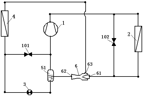
[0033] Specific embodiment 2 such as figure 2 As shown, the second embodiment includes a compressor (1), a condenser (2), a throttling device (3), an evaporator (4), and a first gas-liquid separator (51), and the heat pump system also includes an ejector (6), the first bypass valve (101), the first one-way valve (71), the exhaust port of the compressor (1), the condenser (2), the throttling device (3), the evaporator (4), The inlet of the first gas-liquid separator (51), the outlet of the first gas-liquid separator (51), and the suction port of the compressor (1) are sequentially connected in series to form the first circulation loop of the refrigerant; the outlet of the first bypass valve (101) is connected to the The high-pressure inlet (61) of the ejector (6) is connected, the inlet of the first bypass valve (101) is connected to the inlet of the throttling device (3), the mixing outlet (62) of the ejector (6) is connected to the throttling device ( 3) Outlet connection, ...

specific Embodiment 3

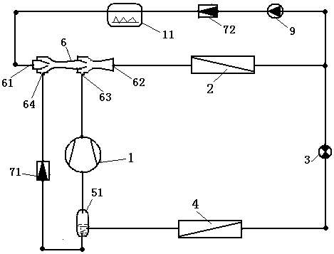
[0036] Specific embodiment 3 such as image 3 As shown, this embodiment 3 includes a compressor (1), a condenser (2), a throttling device (3), an evaporator (4), a first gas-liquid separator (51), an ejector (6), First bypass valve (101), compressor (1) exhaust port, condenser (2), ejector (6) high pressure inlet (61), ejector (6) mixing outlet (62), first The inlet of the gas-liquid separator (51), the gas outlet of the first gas-liquid separator (51), and the suction port of the compressor (1) are sequentially connected in series to form the first circulation loop of the refrigerant; the liquid outlet of the first gas-liquid separator (51) , throttling device (3), evaporator (4), ejector (6) first ejected port (63), ejector (6) mixing outlet (62), first gas-liquid separator (51 ) inlets are sequentially connected in series to form a second circulation loop of refrigerant, and the inlet and outlet of the first bypass valve (101) are respectively connected to the gas outlet o...

specific Embodiment 4

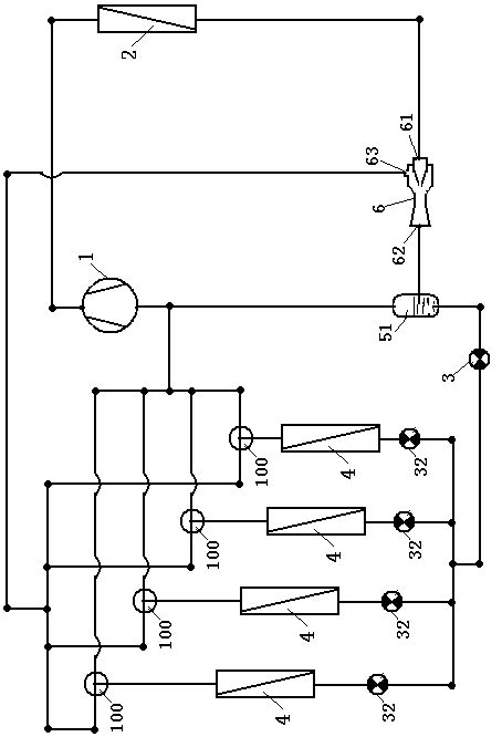
[0041] Specific embodiment 4 such as Figure 4 As shown, Embodiment 4 includes a compressor (1), a condenser (2), a throttling device (3), an evaporator (4), a first gas-liquid separator (51), a second gas-liquid separator ( 52), ejector (6); compressor (1) exhaust port, condenser (2), ejector (6) high pressure inlet (61), ejector (6) mixing outlet (62), the first The inlet of the second gas-liquid separator (52), the liquid outlet of the second gas-liquid separator (52), the throttling device (3), the evaporator (4), the inlet of the first gas-liquid separator (51), the first gas The gas outlet of the liquid separator (51) and the suction port of the compressor (1) are sequentially connected in series to form the first circulation circuit of the refrigerant; the liquid outlet of the first gas-liquid separator (51) and the ejector (6) are first port (63), and the gas outlet of the second gas-liquid separator (52) is connected to the gas supply port of the compressor (1).

[...


PUM


Abstract

The invention discloses a heat pump system with an ejector. The ejector is arranged in an existing heat pump circulating system in series or in parallel, and a liquid refrigerant at the lower part ofa gas-liquid separator or an outlet of an evaporator is ejected by using high-pressure refrigerant, on one hand, the compressor can be effectively prevented from carrying liquid by suction, and liquidimpact damage can be effectively avoided; on the other hand, a heat medium bypass forward circulation mode is adopted, a medium-temperature liquid refrigerant formed by the ejector, a medium-temperature vapor saturated refrigerant in the gas-liquid separator and a superheated vapor refrigerant at an exhaust port of a compressor are sequentially introduced into the evaporator to release heat, defrost and melt ice, the refrigerants at different pressures and temperatures are used in steps to defrost and melt ice, and small temperature difference is uniform to release heat, heat leakage is reduced, and defrost and melt ice efficiency is high; and the operating pressure of the heat pump system changes stably in the defrosting process, the reliability of equipment is improved, and the servicelife of the system is prolonged.

Description

technical field [0001] The invention relates to the field of refrigeration heat pumps, in particular to a heat pump system with an ejector. Background technique [0002] During the heating process of the air source heat pump under low temperature and high humidity conditions or the ice making process of the ice making unit, the surface of the evaporator is frosted and the ice is thicker and thicker, and the heating and ice making performance is gradually reduced, and the system needs to be defrosted and de-iced in time; There are two types of defrosting and deicing methods in the prior art: reverse cycle and hot gas bypass. During the reverse cycle defrosting process, heat is absorbed from the room, resulting in a decrease in indoor temperature, poor indoor thermal comfort, and frequent forward and reverse switching is easy to cause. The four-way valve is damaged, and the compressor has faults such as liquid slamming and oil dilution; the hot gas bypass defrosting method dir...

Claims


Application Information

Patent Timeline
Patent Type & Authority Applications(China)
IPC IPC(8): F25B25/00F25B13/00F25B41/00F25B41/04F25B41/06F25B41/20F25B41/30F25B41/40
CPCF25B25/00F25B13/00F25B2313/02741F25B41/30F25B41/40F25B41/20
Inventor 李晓光袁振红李社红其他发明人请求不公开姓名
Owner 李社红
Why Eureka
Try Eureka