Wind power shaft testing fixture

A technology for wind power and inspection tools, which is applied in the direction of measuring devices, instruments, and mechanical devices, etc., and can solve the problems of low detection efficiency and high cost of wind power shaft inspection tools

Pending Publication Date: 2020-12-01
常州优谷新能源科技股份有限公司
View PDF0 Cites 1 Cited by
  • Summary
  • Abstract
  • Description
  • Claims
  • Application Information

AI Technical Summary

Problems solved by technology

[0003] The technical problem to be solved by the present invention is to solve the technical problems of high cost and low detection efficiency of the traditional wind power shaft inspection tool

Method used


Image

  • Wind power shaft testing fixture
  • Wind power shaft testing fixture
  • Wind power shaft testing fixture

Examples


Embodiment Construction

[0023] The present invention is described in further detail now in conjunction with accompanying drawing. These drawings are all simplified schematic diagrams, which only illustrate the basic structure of the present invention in a schematic manner, so they only show the configurations related to the present invention.

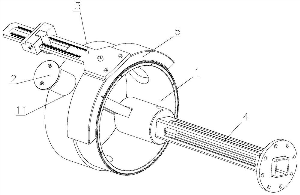
[0024] like figure 1 As shown, the present invention is a wind power shaft inspection tool, including:

[0025] Cylinder 1 is used to socket the wind power shaft, and it is provided with positioning holes 11;

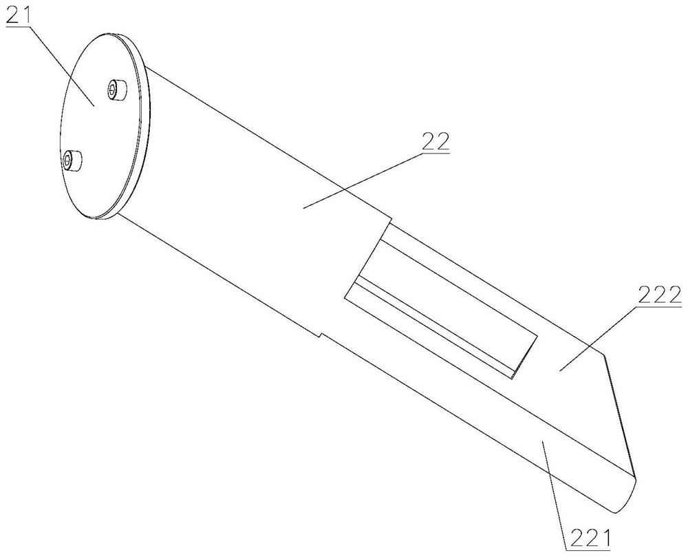
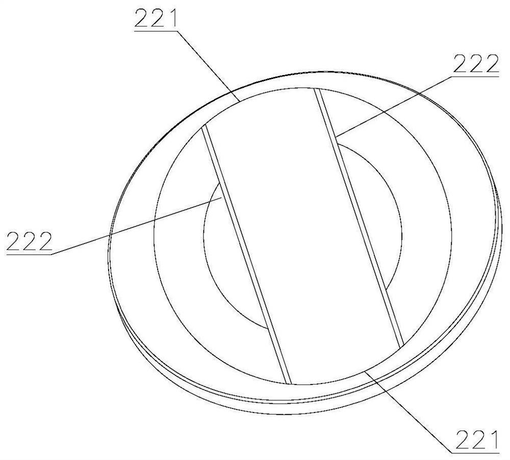
[0026] Positioning device 2, such as figure 2 and image 3 As shown, it includes a baffle plate 21 and a positioning rod 22 connected to each other. The positioning rod 22 is inserted into the positioning hole 11, and the baffle plate 21 is engaged with the positioning hole 11 to realize that the positioning device 2 is fixedly installed on the cylinder body 1, and is used for insertion. Connect the wire holes on the wind power shaft to position th...


PUM


Abstract

The invention relates to a wind power shaft testing fixture, which comprises a cylinder which is used for sleeving a wind power shaft; a positioning device used for being inserted into a wire hole inthe wind power shaft; a measuring device used for clamping a key groove in the wind power shaft and measuring the distance between the key groove and the wire hole; a detection device inserted into the inner hole of the wind power shaft and used for detecting the threaded hole in the end surface of the wind power shaft; and an angle ruler used for measuring an included angle between the wire holeof the wind power shaft and the key groove. Firstly, the wind power shaft is inserted into the cylinder body and fixed under the clamping effect of the positioning device and the wire hole, then the included angle between the wire guide hole of the wind power shaft and the key groove in the radial direction of the wind power shaft is measured through the angle ruler, and the measuring device measures the distance between the key groove and the wire hole in the axial direction of the wind power shaft, so that whether the detected numerical value meets the production requirement is judged. The wind power shaft positioning device, the measuring device and the detection device jointly detect the position relation of the wind power shaft key groove, the wire hole and the end face threaded hole,and the detecting precision is improved.

Description

technical field [0001] The invention relates to the technical field of wind power generators, in particular to a wind power shaft inspection tool. Background technique [0002] There are position requirements for the wind turbine shaft end face, keyway, and wire hole, and the wire hole is an oblique hole, which is difficult to measure. In the past, there will be certain mismeasurements in the measurement, and the inspection tool can only be used for a single model product, which is costly. The position of the end face hole is far away from the position of the wire hole and the keyway, so compound measurement cannot be performed, and the quality control is unstable. Contents of the invention [0003] The technical problem to be solved by the present invention is to solve the technical problems of high cost and low detection efficiency of the traditional wind power shaft inspection tool. [0004] The invention provides a wind power shaft inspection tool, including: [000...

Claims


Application Information

Patent Timeline
Patent Type & Authority Applications(China)
IPC IPC(8): G01B5/00G01B5/14G01B5/24
CPCG01B5/0002G01B5/0018G01B5/003G01B5/14G01B5/24
Inventor 顾永久
Owner 常州优谷新能源科技股份有限公司
Why Eureka
Try Eureka