
Water vapor detection, sampling and cooling tank

A cooling tank and water vapor technology, applied in sampling devices, measuring devices, instruments, etc., can solve problems such as difficulty in ensuring the circumferential sealing of the interface, loose air intake pipes, and popping out of the outer ring of the seal, so as to improve work efficiency and service life. Guaranteed sealing effect

Inactive Publication Date: 2020-12-01
潘景阳
View PDF0 Cites 2 Cited by
  • Summary
  • Abstract
  • Description
  • Claims
  • Application Information

AI Technical Summary

Problems solved by technology

[0003] In view of the above normal conditions, the installer will unavoidably twist a few more turns when turning the intake pipe counterclockwise, and these turns will often cause the intake pipe to completely break away from the threaded hole of the tank nozzle, making the rubber seal between them in compression state, the outer ring of the seal is likely to pop out in the placement groove, causing the seal to be in an over-compressed state for a long time, and the rubber will age in advance, reducing the working efficiency and service life of the equipment. The gas exchange between the tank nozzle and the cooling tank will easily lead to the loosening of the intake pipe on the tank nozzle, and it is difficult to ensure the sealing of the entire interface circumference, which will affect the detection performance of the cooling tank and cannot effectively carry out online continuous monitoring of the sample water Sampling analysis, monitoring problems, the present invention provides a water vapor detection sampling cooling tank

Method used


Image

  • Water vapor detection, sampling and cooling tank
  • Water vapor detection, sampling and cooling tank
  • Water vapor detection, sampling and cooling tank

Examples


Embodiment 1

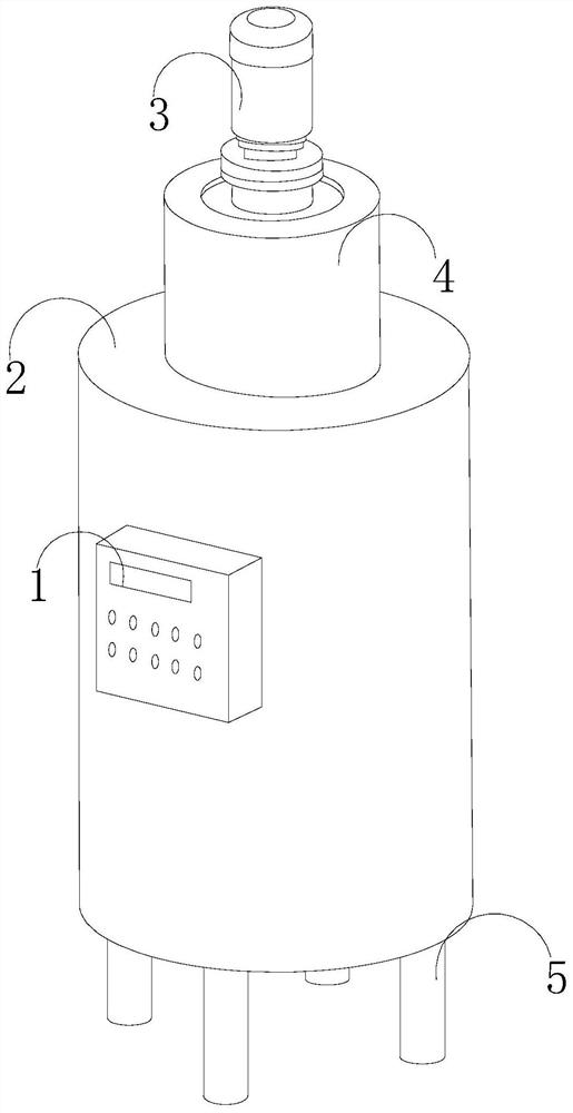
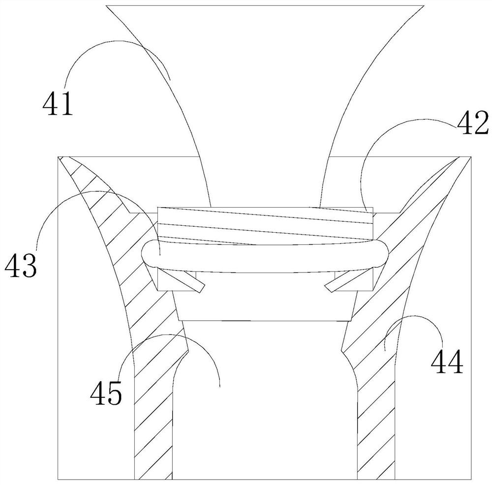
[0030] Such as Figure 1-Figure 4 As shown, the present invention provides a water vapor detection sampling cooling tank, the structure of which includes a control panel 1, a cooling host 2, a motor 3, a sampling introduction structure 4, and a support bracket 5. The control panel 1 is fixedly connected to the outer surface of the cooling host 2 , and the four corners of its bottom are welded to connect with support Jiao 5, and its top is equipped with a sampling introduction structure 4, and the bottom of the sampling introduction structure 4 extends to the inside of the cooling host 2, and is electrically connected with the motor 3, and the sampling introduction structure 4 includes Funnel inlet 41, air inlet pipe 42, top support structure 43, tank mouth 44, container mouth 45, described funnel inlet 41 is fixed with the inside of air inlet pipe 42, described air inlet pipe 42 and tank mouth 44 adopt the mode of threaded connection, two The supporting structure 43 is install...

Embodiment 2

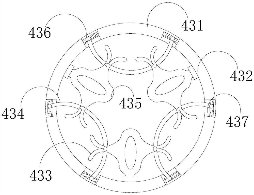
[0032] Such as Figure 5-Figure 7As shown, on the basis of Embodiment 1, the present invention combines the mutual cooperation of the following structural components. The limiting structure 436 includes a support plate 361, a rotating shaft 362, an intermediate piece 363, an expansion spring 364, and a positioning structure 365. The supporting plate 361 is arranged between the expansion spring 364 and the positioning structure 365, and the middle part of the expansion spring 364 is fixed with a rotating shaft 362. , the middle part of the middle part 363 is clearance-fitted on the periphery of the sealing part 437, the positioning structure 365 includes a running-in part 5a1, a crescent plate 5a2, a connecting frame 5a3, and a reinforcing chute 5a4, and the running-in part 5a1 is installed on the reinforcing chute 5a4 In between, two ends of the reinforcement chute 5a4 are fixedly connected with a connecting frame 5a3, and two crescent plates 5a2 are arranged symmetrically ins...


PUM


Abstract

The invention discloses a water vapor detection, sampling and cooling tank, which structurally comprises a control panel, a cooling main machine, a motor, a sampling leading-in structure and a supporting plate, wherein the control panel is fixedly connected to the outer surface of the cooling main machine; supporting feet are welded to four corners of the bottom part of the cooling main machine; asampling leading-in structure is mounted at the top part of the sampling box; and the bottom part of the sampling leading-in structure extends into the cooling main machine, and is electrically connected with the motor. According to the water vapor detection, sampling and cooling tank, a bearing ring is parallel to the axial radius of a placement groove, a lever principle is utilized, certain shaking occurs in the downward pressing process, and a limiting structure intermittently pries a sealing piece on the inner side and extrudes the sealing piece inwards, therefore, the sealing piece cannot be in a compressed state all the time; the phenomenon that an outer ring of the sealing piece pops up in the placement groove is avoided, the vertex angle tentacles abut against each other to form an annular sleeve connected to the bearing ring, and the situation that the connecting rod possibly slides relative to the top ring of the bearing ring, and finally the bearing ring is dragged to be flat and even broken, cannot effectively act on a limiting structure and influences the subsequent process of the structure is avoided.

Description

technical field [0001] The invention relates to the technical field of environmental monitoring, in particular to a cooling tank for water vapor detection and sampling. Background technique [0002] The tank mouth and the intake pipe on the water vapor detection sampling cooling tank are generally sealed by the end face. Only the threaded interface between the two can be used to judge whether the screw is in place. Under normal conditions, the installer will inevitably rotate the intake pipe counterclockwise. When screwing in a few more turns, these turns will often cause the air intake pipe to completely break away from the threaded hole of the tank nozzle, so that the rubber seal between them is in a compressed state, and the outer ring of the seal is prone to pop-up in the placement groove. If the seal is in a state of excessive compression for a long time, the rubber will age in advance, reducing the working efficiency and service life of the equipment. Looseness occurs...

Claims


Application Information

Patent Timeline
Patent Type & Authority Applications(China)
IPC IPC(8): G01N1/22G01N33/00
CPCG01N1/22G01N33/00
Inventor 潘景阳
Owner 潘景阳
Learn More