Supercharge Your Innovation With Domain-Expert AI Agents!

Filtering assembly used in lens module

A technology for lens modules and components, applied in the direction of filters, optical components, optics, etc. for photography, which can solve the problems of spacer ring deformation, filter breakage, offset and other problems

Inactive Publication Date: 2020-12-01
KUNSHAN KANGLONG ELECTRONICS TECH CO LTD +1
View PDF11 Cites 0 Cited by
  • Summary
  • Abstract
  • Description
  • Claims
  • Application Information

AI Technical Summary

Problems solved by technology

[0004] In the aforementioned patent case, although the optical filter can be prevented from falling off from the spacer ring, since the spacer ring is directly formed on the periphery of the optical filter by injection molding, when the optical filter is placed on a In the injection mold, in order to avoid the phenomenon of plastic material escaping in the injection mold, it is necessary to generate a certain clamping force on the filter through the injection mold, so that it is easy to cause the filter in the injection mold Cracks in the mold
In addition, during the cooling process of the plastic material, the spacer ring is easily deformed due to the cooling process, so that when the spacer ring is assembled in the lens module, it will cause deviation, which will affect the imaging quality of the lens module

Method used


Image

  • Filtering assembly used in lens module
  • Filtering assembly used in lens module
  • Filtering assembly used in lens module

Examples


Embodiment Construction

[0041] Relevant detailed description and technical content of the present invention, cooperate accompanying drawing to illustrate as follows now:

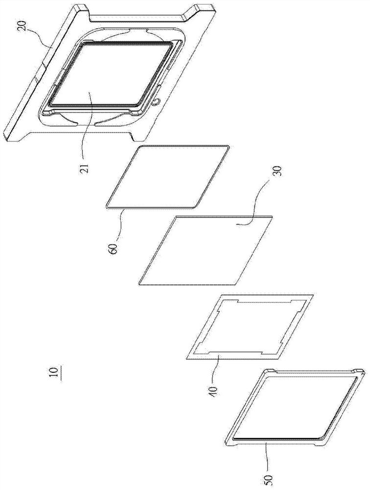
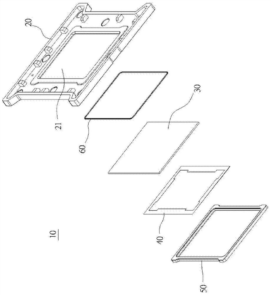
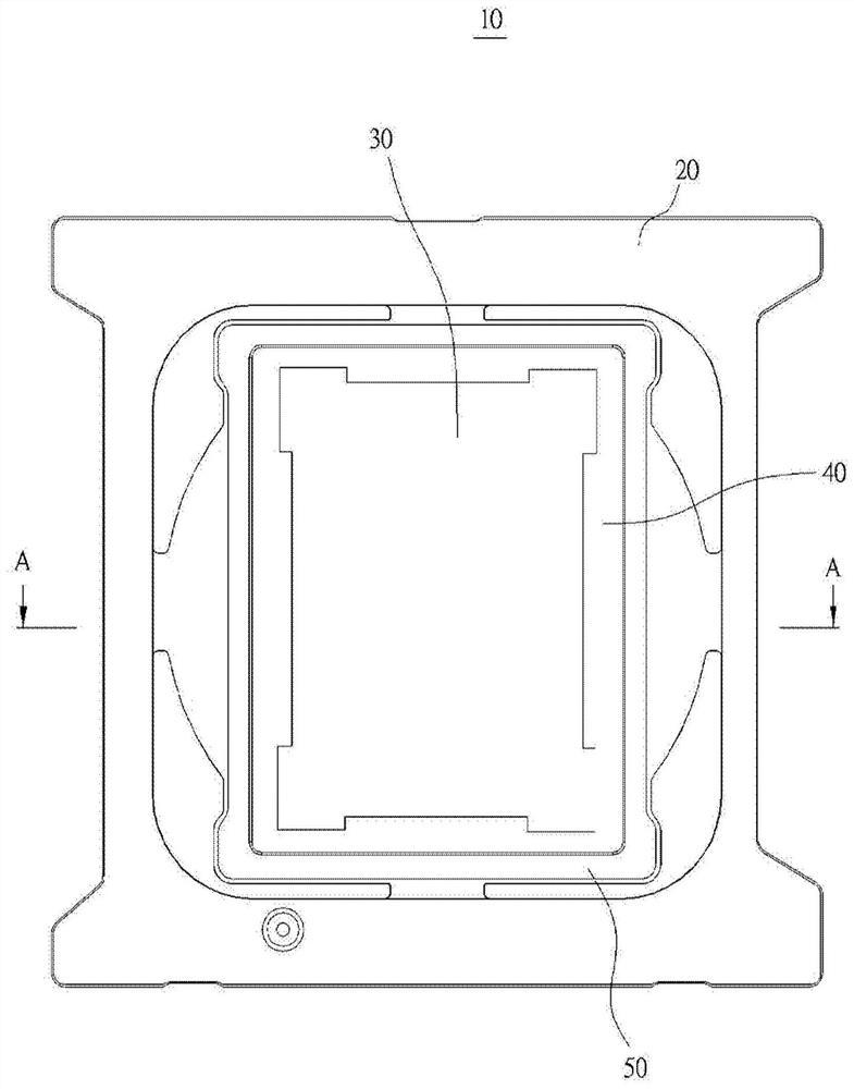
[0042] Such as Figure 1 to Figure 5 As shown, the present invention is a filter assembly used in a lens module, the filter assembly 10 includes a fixing seat 20, a filter 30, a light shield 40, a contact 50 and an auxiliary contact 60.

[0043] The fixing base 20 is formed by injection molding of a plastic material. The fixing base 20 has a hollow part 21 in the center, and the hollow part 21 is a support extending from the fixing base 20 toward the hollow part 21. A first contact space 23 is formed between the supporting portion 22 and the fixing base 20 . In addition, a support platform 24 is further formed on the support portion 21, and a second contact space 25 is provided on the support platform 24.

[0044] The optical filter 30 is mounted on the hollow portion 21 and carried on the supporting platform 24 of the supportin...


PUM


Abstract

A filtering assembly is used for being installed in a lens module and comprises a fixing base with a hollow portion, a light filtering piece arranged at the position of the hollow portion, an annularlight shielding piece arranged on the light filtering piece and a contact piece. The hollow portion is formed by annularly arranging a supporting part extending from the fixing base to the hollow portion; and a first contact space capable of enabling the outer peripheral edges of the optical filter and the light shielding piece to extend into the first contact space is formed between the supporting part and the fixing base. The contact piece is formed in the contact space by injecting an adhesive material into the first contact space and cooling, so that the optical filter and the shading piece are stopped at the position of the hollow part, and the optical filter and the shading piece are fixed on the fixing base.

Description

technical field [0001] The present invention relates to an optical filter assembly, in particular to an optical filter assembly which is applied in a lens module, can improve the assembly efficiency of the lens module, and can greatly reduce labor costs. Background technique [0002] The optical filter is mainly installed in a lens module to filter light, thereby ensuring that the lens module has good imaging quality. The traditional optical filter is mainly glued on a spacer ring by dispensing glue with a glue dispenser. The traditional dispensing method is prone to poor contact between the optical filter and the spacer ring due to problems such as deterioration of the adhesive, uneven coating, or incomplete curing, resulting in poor contact between the optical filter and the spacer ring. The phenomenon of peeling between the spacer rings makes the lens module invalid, resulting in poor production efficiency. [0003] In addition, as Taiwan Patent No. I366737, a lens modu...

Claims


Application Information

Patent Timeline
Patent Type & Authority Applications(China)
IPC IPC(8): G03B11/00G02B7/00
CPCG03B11/00G02B7/006G02B7/00
Inventor 庄艳奎杨恒
Owner KUNSHAN KANGLONG ELECTRONICS TECH CO LTD
Features
  • R&D
  • Intellectual Property
  • Life Sciences
  • Materials
  • Tech Scout
  • Unparalleled Data Quality
  • Higher Quality Content
  • 60% Fewer Hallucinations
Learn More