Bladder circulation continuous flushing device

A technique for irrigating a device and a bladder, applied in the field of irrigators, can solve the problems of prolonging operation time, patient trauma, increasing the patient's economic burden, etc., and achieves the advantages of not easily excessive intravesical pressure, preventing reflux back to the bladder, and improving operation safety. Effect

Active Publication Date: 2020-12-04
WUHAN UNIV
View PDF8 Cites 0 Cited by
  • Summary
  • Abstract
  • Description
  • Claims
  • Application Information

AI Technical Summary

Problems solved by technology

In the prior art, when the bladder is flushed, there needs to be a continuous flushing liquid to ensure water circulation, which not only wastes a lot of resources, but also increases the economic burden of the patient, and the use of a large amount of flushing liquid can easily cause water intoxication of the patient, and in severe cases, life-threatening ; Moreover, most of the existing ellik irrigators are single-channel. During the rinsing process, the irrigating material is easy to flow back into the bladder, and repeated flushing is required, which is inefficient, prolongs the operation time, and increases the risk of the operation; in addition, with the ellik The extrusion rule of the irrigator, due to the large rise and fall of the pressure in the bladder, can easily cause the pressure in the bladder to be too high, which will involve the surgical wound and cause bleeding. In severe cases, the bladder will rupture, causing greater trauma and pain to the patient.

Method used


Image

  • Bladder circulation continuous flushing device
  • Bladder circulation continuous flushing device
  • Bladder circulation continuous flushing device

Examples


Embodiment Construction

[0020] Specific embodiments of the present invention are described in detail below, which, as a part of the description, illustrate the principles of the present invention through examples, and other aspects, features and advantages of the present invention will become apparent through the detailed description.

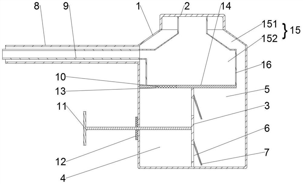
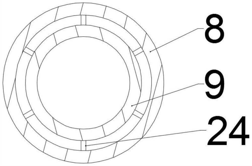
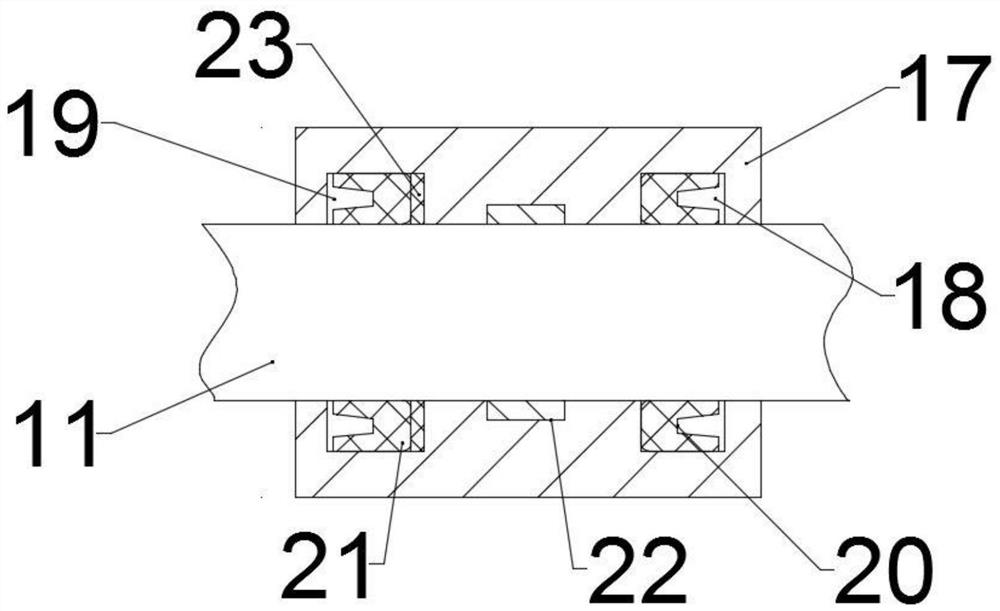
[0021] Example. A bladder cycle continuous flushing device, consisting of Figure 1-5 As shown, the washing bottle 1 is included, and the washing bottle 1 is connected with a detachable bottle cap 2. The bottle cap 2 is arranged on the top of the washing bottle 1, and a partition 14 with a round hole 13 is arranged in the washing bottle 1. A filter screen 10 is provided in the hole 13; the upper flow chamber 15 and the lower flushing area are separated by the partition plate 14 in the rinse bottle 1, and a soft membrane 3 is arranged in the lower flushing area, and the upper end of the soft membrane 3 is connected with the partition plate 14 , the lower end of the so...


PUM


Abstract

The invention discloses a bladder circulation continuous flushing device. The bladder circulation continuous flushing device comprises a flushing bottle, wherein the flushing bottle is connected witha bottle cap, and a partition plate is arranged in the flushing bottle; the flushing bottle is divided into an upper flowing chamber and a lower flushing area by the partition plate, a soft film is arranged in the lower flushing area, the upper end of the soft film is connected with the partition plate, the lower end of the soft film is connected with the bottom of the flushing bottle, and the lower flushing area is divided into a filtering chamber and a flushing chamber by the soft film; an annular wall is arranged in the upper flowing chamber, the upper flowing chamber is divided into an inner cavity and an outer cavity by the annular wall, and the outer cavity communicates with the flushing chamber; and the upper end of the inner cavity communicates with the bottle opening of the flushing bottle, and the lower end of the inner cavity communicates with the filtering chamber through a filter screen. The bladder circulation continuous flushing device can be used for quickly cleaning the bladder, the use of flushing liquid can be reduced, resources are saved, and the operation time is shortened; meanwhile, the pressure in the bladder cannot be greatly changed, and the wear resistance of a push rod can be improved.

Description

technical field [0001] The invention relates to the technical field of flushing devices, in particular to a bladder cycle continuous flushing device. Background technique [0002] Clinically, when dealing with urinary system tumor bleeding, transurethral resection of the prostate, transurethral bladder tumor resection, transurethral bladder lithotripsy, etc., it is necessary to treat blood clots, chopped tissue blocks and stones in the bladder Debris etc. are rinsed. The irrigator that is often used at present is the ellik irrigator. In the prior art, when the bladder is flushed, there needs to be a continuous flushing liquid to ensure water circulation, which not only wastes a lot of resources, but also increases the economic burden of the patient, and the use of a large amount of flushing liquid can easily cause water intoxication of the patient, and in severe cases, life-threatening ; Moreover, most of the existing ellik irrigators are single-channel. During the rinsing...

Claims


Application Information

Patent Timeline
Patent Type & Authority Applications(China)
IPC IPC(8): A61M3/02
CPCA61M3/0229A61M2205/7545A61M2205/3341A61M2210/1085A61M2210/005
Inventor 陈永顺时振国朱小娟柯少波邱虎李彬蔡高科
Owner WUHAN UNIV
Why Eureka
Try Eureka