Anesthetic gas concentration monitoring device

A technology of concentration monitoring and anesthetic gas, applied in the field of medical devices, can solve the problems of installation restrictions, affecting work efficiency, affecting use, etc., to ensure normal use, facilitate cleaning and maintenance, and increase applicability.

Pending Publication Date: 2020-12-04
林常森
View PDF6 Cites 0 Cited by
  • Summary
  • Abstract
  • Description
  • Claims
  • Application Information

AI Technical Summary

Problems solved by technology

[0002] Medical devices refer to instruments, equipment, utensils, in vitro diagnostic reagents and calibrators, materials, and other similar or related items that are directly or indirectly used on the human body, including the required computer software. The utility is mainly obtained through physical means, not through Obtained by means of pharmacology, immunology or metabolism, or although these methods are involved, they only play an auxiliary role. As an instrumentation tool for gas concentration detection, gas detectors are widely used in the field of clinical anesthesia. By detecting gas concentrations, To ensure the working efficiency of medical staff, during gas anesthesia, a metal tube will be set outside the intake pipe for protection, which leads to restrictions on the installation of the monitor, and it is impossible to make adjustments and adjustments according to the terrain space and special conditions. Changes will affect the use, and after the installation is completed, the medical staff cannot judge the use of the filter in the monitor, and frequent disassembly and assembly are required for inspection and maintenance, which affects operating efficiency

Method used


Image

  • Anesthetic gas concentration monitoring device
  • Anesthetic gas concentration monitoring device
  • Anesthetic gas concentration monitoring device

Examples


Embodiment 1

[0028] Such as Figure 1 to Figure 7 shown;

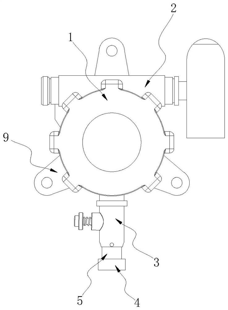
[0029] figure 1 It is a structural schematic diagram of the present invention;

[0030] figure 2 It is a schematic diagram of the structure between the connecting pipe and the flexible pipe in the present invention;

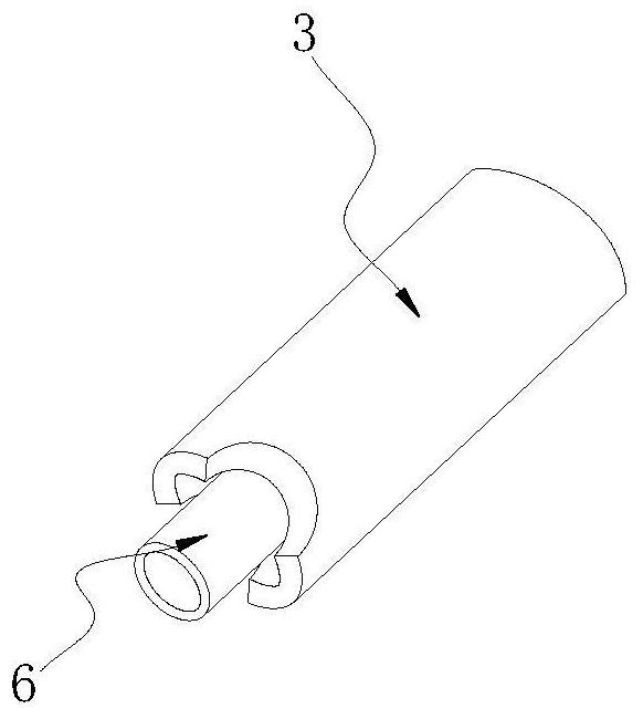
[0031] image 3 It is a schematic diagram of the structure between the movable pipe and the flexible pipe in the present invention;

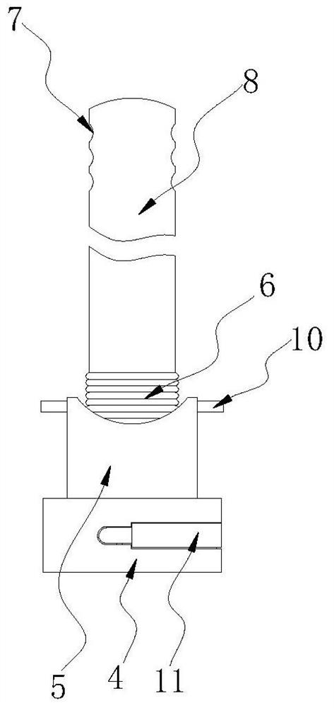
[0032] Figure 4 It is a schematic diagram of the structure between the casing and the sleeve plate in the present invention;

[0033] Figure 5 It is a structural schematic diagram of a ferrule and a plug in the present invention;

[0034] Figure 6 It is a schematic cross-sectional structure diagram of the casing in the present invention;

[0035] Figure 7 It is an enlarged view of A in the present invention.

[0036] An anesthetic gas concentration monitoring device, comprising a detector body 1, a connecting pipe 2 and a mounting plate 9, the connecting pipe 2 is locat...


PUM


Abstract

The invention belongs to the technical field of medical instruments, and particularly relates to an anesthetic gas concentration monitoring device. The anesthetic gas concentration monitoring device comprises a detector body, a communicating tube and mounting plates, wherein the communicating tube is located at the top of the detector body and fixedly connected with the detector body; and the mounting plates are symmetrically distributed on the back face of the outer side wall of the detector body, and are fixedly connected with the detector body; and a connecting tube is arranged at the bottom of the detector body in a sleeving manner. A sleeve plate is pushed to rotate to drive a sleeve hoop to move out of a sleeve tube, so that a filter screen is exposed, and people can conveniently master the use condition of the filter screen in real time and conveniently clean and maintain the filter screen; when the sleeve hoop enters the sleeve tube, springs are stressed to extend to push movable rods to get close to each other along sliding rods until a sleeve plug is embedded into a base plate, so that the sleeve plug is fixed, the sleeve hoop is prevented from moving out of the sleeve tube, and sealing is guaranteed; and external bolts can be connected with the movable rods, so that the movable rods can be fixed, and the sealing firmness is improved.

Description

technical field [0001] The invention belongs to the technical field of medical devices, and in particular relates to an anesthetic gas concentration monitoring device. Background technique [0002] Medical devices refer to instruments, equipment, utensils, in vitro diagnostic reagents and calibrators, materials, and other similar or related items that are directly or indirectly used on the human body, including the required computer software. The utility is mainly obtained through physical means, not through Obtained by means of pharmacology, immunology or metabolism, or although these methods are involved, they only play an auxiliary role. As an instrumentation tool for gas concentration detection, gas detectors are widely used in the field of clinical anesthesia. By detecting gas concentrations, To ensure the working efficiency of medical staff, during gas anesthesia, a metal tube will be set outside the intake pipe for protection, which leads to restrictions on the instal...

Claims


Application Information

Patent Timeline
Patent Type & Authority Applications(China)
IPC IPC(8): A61M16/10A61M16/00
CPCA61M16/1005A61M16/0003A61M2016/1025
Inventor 林常森
Owner 林常森
Why Eureka
Try Eureka