Stone brick cutting equipment

A cutting equipment, stone brick technology, applied in stone processing equipment, stone processing tools, work accessories, etc., can solve the problems of high cutting risk, low efficiency, easy fatigue, etc., and achieve the effect of improving work efficiency and ensuring safety.

Active Publication Date: 2020-12-04
东莞市创建新型建材有限公司
View PDF12 Cites 3 Cited by
  • Summary
  • Abstract
  • Description
  • Claims
  • Application Information

AI Technical Summary

Problems solved by technology

[0003] At present, people cut stone bricks by manually pushing the stone bricks to the cutting machine for cutting. It is necessary to control the force so that the thickness of each stone brick is about the same. Working non-stop makes people tired easily and inefficient

Method used


Image

  • Stone brick cutting equipment
  • Stone brick cutting equipment
  • Stone brick cutting equipment

Examples


Embodiment 1

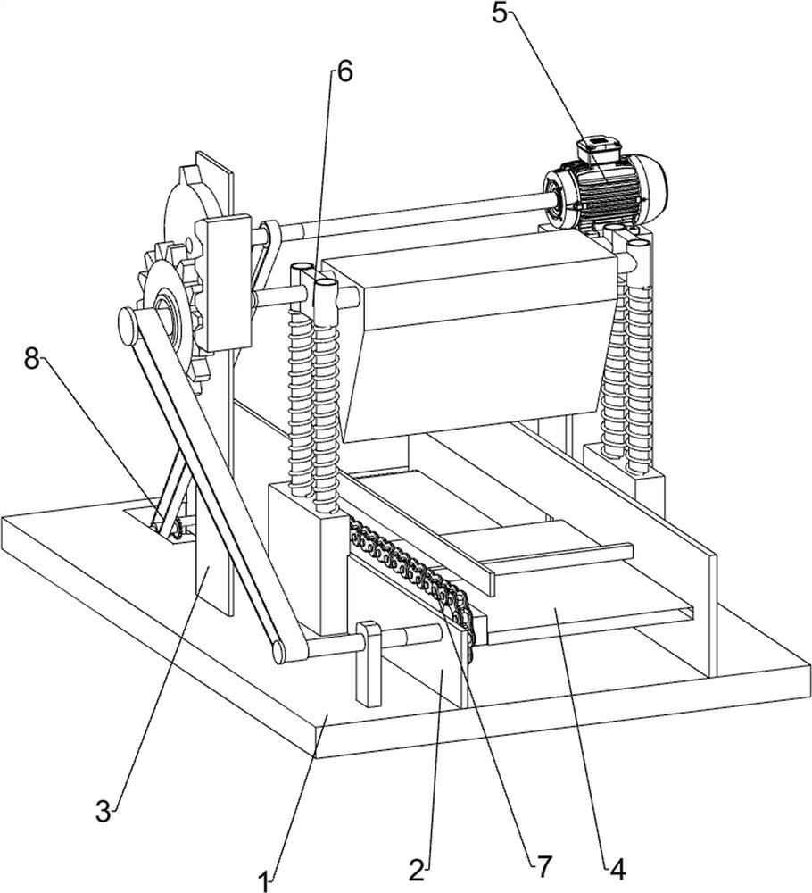
[0024] A stone brick cutting equipment such as figure 1 , 2 As shown, it includes a placement board 1, a side board 2, a bracket 3, a supporting board 4, a drive assembly 5 and a cutting assembly 6. The inner side of the middle part of the plate 2 is connected with a supporting plate 4 , the rear side of the top of the placing plate 1 is provided with a drive assembly 5 , and the middle of the top of the placing plate 1 is connected with a cutting assembly 6 .

[0025] The driving assembly 5 includes a motor 51 and a first rotating shaft 52 , the top right side of the placing plate 1 is provided with a motor 51 , the output shaft of the motor 51 is connected with a first rotating shaft 52 , and the first rotating shaft 52 is rotationally connected with the upper side of the support 3 .

[0026] The cutting assembly 6 includes a slide bar 61, a slide block 62, a return spring 63, a cutting tool 64, a rack 65 and a three-toothed gear 66, and two slide bars 61 are slidably conne...

Embodiment 2

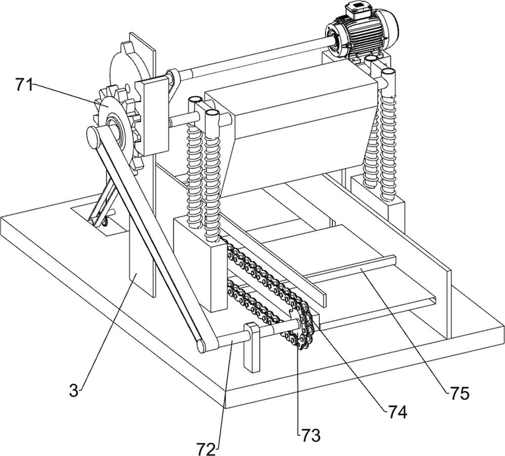
[0029] On the basis of Example 1, such as image 3 As shown, a push assembly 7 is also included, and the push assembly 7 includes a one-way gear 71, a second rotating shaft 72, a sprocket 73, a chain 74 and a push rod 75, and the left side of the bracket 3 is connected with a one-way gear 71 in a rotational manner, The one-way gear 71 meshes with the rack 65, the top front end of the placement plate 1 is rotatably connected with a second rotating shaft 72, and the second rotating shaft 72 is transmission-connected with the one-way gear 71, and the front and rear sides of the left end of the side plate 2 are rotatably connected with sprockets 73. The right end of the second rotating shaft 72 is connected with the front sprocket 73, and a chain 74 is wound between the sprockets 73 on both sides. The right end of the chain 74 is diagonally connected with two push rods 75.

[0030] When the tooth bar 65 moves upwards through the return spring 63, it drives the one-way gear 71 to r...


PUM


Abstract

The invention relates to cutting equipment, in particular to stone brick cutting equipment. The technical problem to be solved by the invention is to provide the safe and efficient stone brick cuttingequipment which does not need manual pushing and ensure the thickness of each stone brick to be the same. In order to solve the technical problem, the invention provides the stone brick cutting equipment which comprises a placing plate, a bracket, a supporting plate, a driving device and a cutting device. Side plates are connected onto the placing plate; the bracket is connected to one side of the top part of the placing plate; the supporting plate is connected between the side plates;the driving assembly is connected to one side of the top part of the placing plate; and the cutting assemblyis connected on to the placing plate. Through the cooperation of the driving assembly, the cutting assembly and a pushing assembly, continuous automatic cutting is achieved, and stone bricks do not need to be pushed manually to be cut, so that the safety of workers is guaranteed, and the working efficiency is improved.

Description

technical field [0001] The invention relates to a cutting device, in particular to a stone brick cutting device. Background technique [0002] Stone brick is a kind of high-end interior building decoration material composed of natural stone and ceramic plate. In summary. Stone bricks have the advantages of natural marble, luxurious atmosphere, natural texture and natural texture, while avoiding some defects of the marble version. Relatively speaking, stone bricks are more uniform in design and color, strong in waterproof and anti-fouling, higher in strength and lighter in weight. It is light, more convenient to install, and can effectively avoid shortcomings such as alkali return, seepage, and cracking. It has become a natural decorative material favored by high-end consumer groups. [0003] At present, people cut stone bricks by manually pushing the stone bricks to the cutting machine for cutting. It is necessary to control the force so that the thickness of each stone br...

Claims


Application Information

Patent Timeline
Patent Type & Authority Applications(China)
IPC IPC(8): B28D1/22B28D7/04
CPCB28D1/22B28D7/04
Inventor 钟佐荣
Owner 东莞市创建新型建材有限公司
Why Eureka
Try Eureka