Eureka AIR delivers breakthrough ideas for toughest innovation challenges, trusted by R&D personnel around the world.

Movable automatic protection system in existing railway line construction

An automatic protection and construction technology, applied in railway signaling and safety, etc., can solve problems such as lack of outlook and potential safety hazards, and achieve the effect of cost-effective protection

Pending Publication Date: 2020-12-04
李淑杰
View PDF0 Cites 0 Cited by
  • Summary
  • Abstract
  • Description
  • Claims
  • Application Information

AI Technical Summary

Problems solved by technology

[0002] At present, when our country is involved in the construction of existing railway lines or adjacent existing lines, artificial protection measures are adopted. A protection system includes at least 4 people: 1 station liaison officer, 2 remote protection personnel and 1 on-site protection personnel. In severe weather such as heavy fog, there are problems such as insufficient lookout, and there are potential safety hazards

Method used


Image

  • Movable automatic protection system in existing railway line construction
  • Movable automatic protection system in existing railway line construction
  • Movable automatic protection system in existing railway line construction

Examples


Embodiment 1

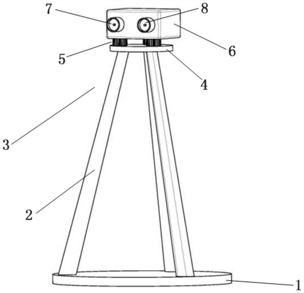
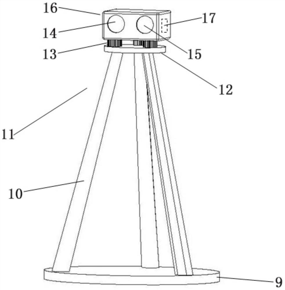
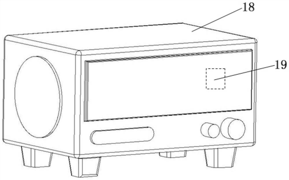
[0036] Such as Figure 1-Figure 8 As shown, a mobile automatic protection system in the construction of an existing railway line includes an infrared transmitter 3 , an infrared receiver 11 and a loudspeaker 18 .

[0037] The infrared receiver 11 is connected to the loudspeaker 18 through electromagnetic waves.

[0038] Described infrared emitter 3 comprises infrared emitter box 6, is provided with a left infrared emitter 8 and a right infrared emitter 7 in parallel in described infrared emitter box 6, also on the side wall of described infrared emitter box 6 A signal lamp 20 is provided.

[0039] The bottom of the infrared emitter box 6 is fixed on an emitter chassis 4 by three emitter adjustment screws 5, and the bottom of the emitter chassis 4 is provided with three emitter legs 2, three emitter legs 2 The base is also fastened to a transmitter base 1 .

[0040] The infrared receiver 11 includes an infrared receiver box 16, and a left infrared receiver 15 and a right inf...

Embodiment 2

[0052] Such as Figure 9-Figure 13 As shown, further, the left infrared emitter 8 and the right infrared emitter 7 of the infrared emitter 3 of this patent can also be changed into two identical left infrared emitter receivers 25 and right infrared emitters with functions of infrared emission and reception. The form of transmitting receiver 26 forms a total infrared transmitting receiver 27, cancels infrared receiver 11, and then arranges a total infrared transmitting receiver 27 respectively on both sides of the construction area, according to the left infrared transmitting receiver 27 of the total infrared transmitting receiver 27 Whether the sensor or the right infrared transmitting receiver is blocked first to judge the direction of the coming vehicle.


PUM


Abstract

The invention discloses a movable automatic protection system in existing railway line construction. The movable automatic protection system comprises an infrared emitter, an infrared receiver and a loudspeaker. The infrared emitter comprises an infrared emitter box, a left infrared emitter and a right infrared emitter are arranged in the infrared emitter box in parallel, and a signal lamp is further arranged on the side wall of the infrared emitter box. The infrared receiver comprises an infrared receiver box, and a left infrared receiver and a right infrared receiver are arranged in the infrared receiver box in parallel. According to the system, the problem of safety accidents caused by insufficient lookout or poor responsibility of protection personnel is solved, meanwhile, the system can replace two far-end protection personnel, and the protection cost is more economical.

Description

technical field [0001] The invention relates to the technical field of railway construction protection, in particular to a movable automatic protection system in the construction of existing railway lines. Background technique [0002] At present, when our country is involved in the construction of existing railway lines or adjacent existing lines, manual protection measures are adopted. A protection system includes at least 4 people: 1 station liaison officer, 2 remote protection personnel and 1 on-site protection personnel. In severe weather such as heavy fog, there are problems such as insufficient lookout, and there are potential safety hazards. Contents of the invention [0003] The purpose of the present invention is to solve the shortcomings in the prior art, and propose a movable automatic protection system in the construction of existing railway lines. [0004] In order to achieve the above object, the present invention adopts the following technical solutions: a...

Claims


Application Information

Patent Timeline
IPC IPC(8): B61L23/06
CPCB61L23/06
Inventor 李淑杰吴彩凤张春贤刘琦尹聪李淑慧
Owner 李淑杰
Why Eureka
Eureka Blog
Learn More