
Rotor blade tip clearance control method and rotor blade manufactured by the method

A technology of rotor blade and control method, applied in the field of rotor blade tip clearance control and rotor blade field, can solve the problem of uneven radial displacement of rotor blade tip, and achieve the effect of improving aerodynamic performance parameters

Active Publication Date: 2021-01-29
AECC SHANGHAI COMML AIRCRAFT ENGINE MFG CO LTD +1
View PDF2 Cites 0 Cited by
  • Summary
  • Abstract
  • Description
  • Claims
  • Application Information

AI Technical Summary

Problems solved by technology

[0012] The purpose of the present invention is to provide a rotor tip clearance control method that can effectively improve the inconsistent radial displacement of the leading edge and trailing edge of the rotor tip during operation

Method used


Image

  • Rotor blade tip clearance control method and rotor blade manufactured by the method
  • Rotor blade tip clearance control method and rotor blade manufactured by the method
  • Rotor blade tip clearance control method and rotor blade manufactured by the method

Examples


Embodiment Construction

[0059]The steps of the rotor blade tip clearance control method according to the present invention, as well as the structure and effect of the rotor blade manufactured by the method will be described below with reference to the accompanying drawings, wherein the same components are marked by the same reference numerals.

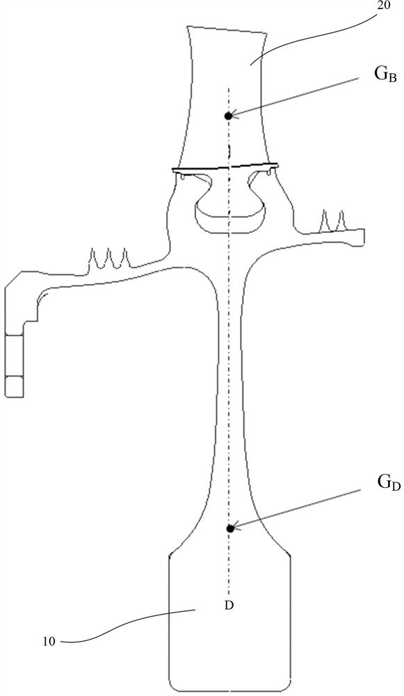
[0060] figure 1 A rotor disk 10 with an unshifted center of gravity is shown, on which several rotor blades 20 are mounted, and for ease of illustration, only one rotor blade 20 is shown in this figure.

[0061] As we all know, the rotating body supported by bearings during high-speed rotation is called a rotor, and the rotor is the main rotating part in the field of power machinery such as electric motors, generators, gas turbines, turbocompressors and compressors. The rotor can rotate around its axis, the extending direction of the axis is called the axial direction of the rotor, and the direction extending radially from the axis vertically is called the ra...


PUM


Abstract

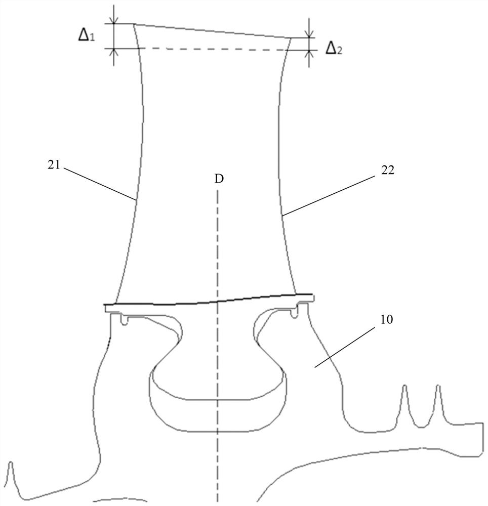
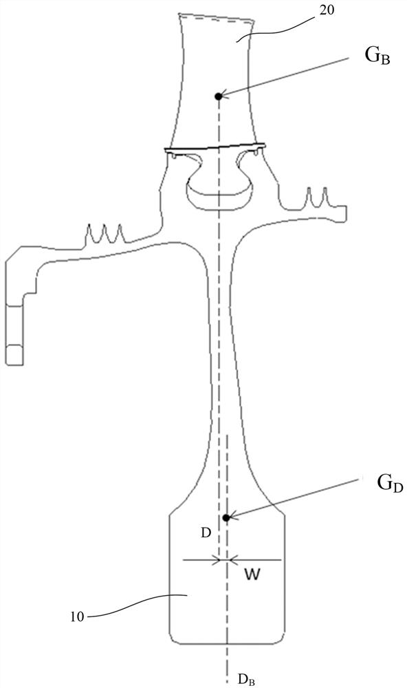
The invention relates to a rotor blade tip clearance control method, comprising the following steps: making the center of gravity (G) of the rotor blade (20) B ) and the center of gravity (G D ) coincide in the axial direction (D) of the aero-engine; make the rotor disc (10) rotate, and measure the leading edge deformation (Δ 1 ); measure the trailing edge deformation of the trailing edge (22) of the rotor blade (20) (Δ 2 ); compare the deformation of the leading edge (Δ 1 ) and trailing edge deformation (Δ 2 ); adjust the center of gravity (G D ), until the deformation of the leading edge (Δ 1 ) and trailing edge deformation (Δ 2 ) tend to be roughly equal. This method can effectively improve or even solve the problem of inconsistency in the radial displacement of the leading edge and the trailing edge of the rotor blade tip during operation.

Description

technical field [0001] The invention relates to a rotor blade tip clearance control method and a rotor blade manufactured by the method. Background technique [0002] The compressor is a component in a gas turbine engine that uses high-speed rotating impeller blades (or "rotor blades") to work on the air to increase the air pressure. The supercharging stage is a compressor stage specially arranged between the fan and the compressor to improve the aerodynamic performance of the front fan and the compressor and increase the pressure at the inlet of the compressor. Supercharged compressors are usually used as aero engines, and the front end of the rotor blades (or called "blade tip" or "rotor tip") is usually curved, and its role is to introduce gas into the working area without impact. The rotor reduces the kinetic energy loss caused by the impact of the airflow. [0003] The compressor casing has inlets and outlets for the airflow to enter and exit. The casing inlet is usu...

Claims


Application Information

Patent Timeline
Patent Type & Authority Patents(China)
IPC IPC(8): F04D29/32F04D29/38
CPCF04D29/321F04D29/324F04D29/322F04D27/001F04D29/642F04D29/526F01D11/16F01D5/3038F05D2250/73F01D5/141F01D21/003F01D5/02F05D2270/821F05D2240/303F05D2240/304G01M1/122G01M15/14F01D5/021F01D11/22F04D19/002F05D2220/323F05D2230/80F05D2240/55F01D5/14Y10T29/49771F01D11/14B23P15/006B23P15/02Y10T29/49336F05D2260/83
Inventor 王家广胡淑慧秦文曹传军吴志青
Owner AECC SHANGHAI COMML AIRCRAFT ENGINE MFG CO LTD
Learn More