A hydraulic shift control system for an automatic transmission of a motor vehicle
A technology of automatic transmission and shift control, applied in control/regulation systems, vehicle gearboxes, mechanical control devices, etc., can solve the problems of increasing gears, high pressure, energy consumption, etc., and achieve stable pressure, simple structure, and cost. low effect
- Summary
- Abstract
- Description
- Claims
- Application Information
AI Technical Summary
Problems solved by technology
Method used
Image

Examples
Embodiment 1
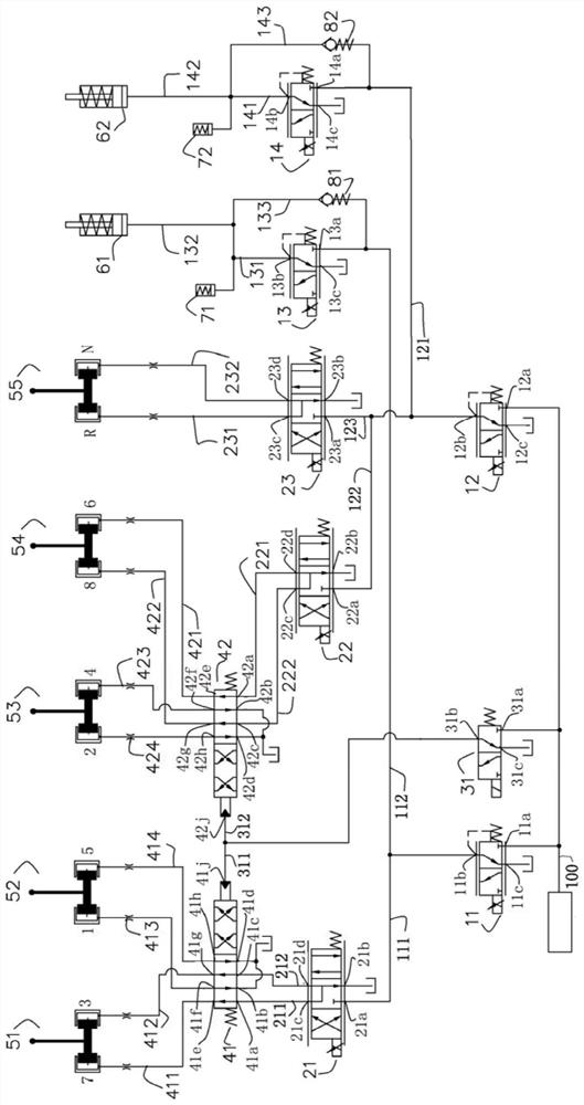
[0024] Please refer to the attached figure 1 , a hydraulic shift control system for an automatic transmission of a motor vehicle provided by the present invention includes a clutch device and a gear adjustment device respectively connected to a pressure source, and the clutch device includes a first clutch and a second clutch , between the pressure source and the first clutch, and between the pressure source and the second clutch are respectively provided with pressure control solenoid valves; the gear adjustment device includes a first gear switching slide valve 41 , the second gear conversion slide valve 42, the gear switch solenoid valve 31 and at least five shift forks, the gear switch solenoid valve 31 is connected with the pressure source and used to select the first gear every time One of the switching spool valve 41 and the second gear switching spool valve 42, the first gear switching spool valve 41 controls the displacement of the first shift fork 51 and the second s...
Embodiment 2
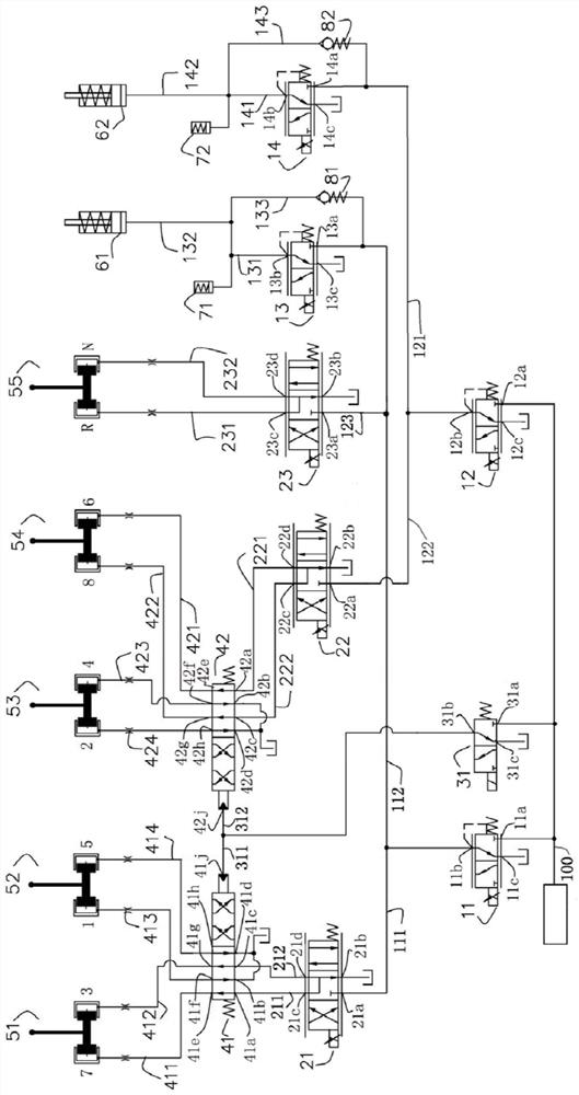
[0061] Please refer to the attached figure 2 The difference between this embodiment and the first embodiment is that the input end of the third flow control solenoid valve 23 is connected to the first pressure control solenoid valve 11 instead of the second pressure control solenoid valve 12 .
[0062] During its working process, in order to realize the function of the R gear, the first pressure solenoid valve 11 is energized, and the input port 11a is connected to the output port 11b. According to the pressure demand, the current is controlled, and the output port 11b outputs the target pressure, and the oil path 113 leads to The input port 23a of the third flow control solenoid valve 23 leads to the input port 13a of the third pressure control solenoid valve 13 through the oil passage 112; the current of the third flow control solenoid valve is controlled so that it is in position one, and the input port 23a communicates The output port 23c can control the output flow rate ...
Embodiment 3
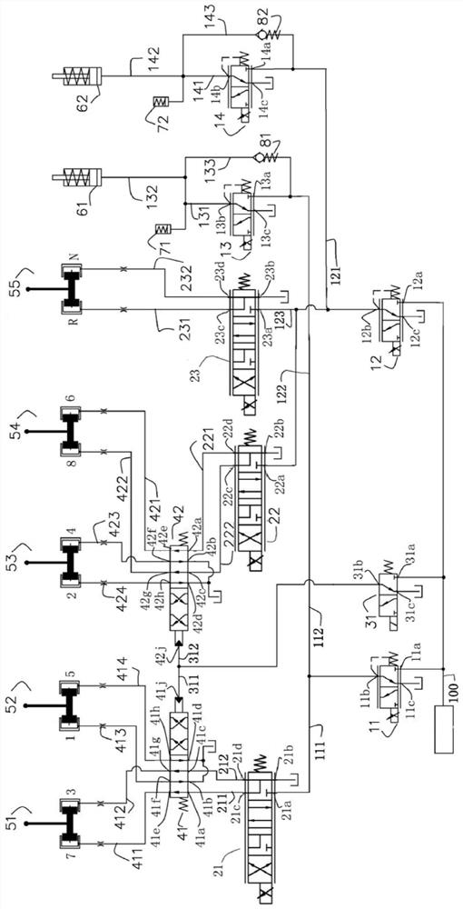
[0064] Please refer to the attached image 3 , The difference between this embodiment and Embodiment 1 is that the flow control solenoid valve is replaced by a three-position four-way with a four-position four-way, but its function is the same. The flow control solenoid valve has four positions from right to left, and its position 1 and position 3 have the same function as position 2 of the flow control solenoid valve of the first embodiment, and its position 2 is the same as that of the flow control solenoid valve of the first embodiment. Position 1 has the same function, and position 4 has the same function as position 3 of the flow control solenoid valve in Embodiment 1.
PUM
 Abstract
Description
Claims
Application Information
 - R&D
- Intellectual Property
- Life Sciences
- Materials
- Tech Scout
- Unparalleled Data Quality
- Higher Quality Content
- 60% Fewer Hallucinations
Browse by: Latest US Patents, China's latest patents, Technical Efficacy Thesaurus, Application Domain, Technology Topic, Popular Technical Reports.
© 2025 PatSnap. All rights reserved.Legal|Privacy policy|Modern Slavery Act Transparency Statement|Sitemap|About US| Contact US: help@patsnap.com