
Gas heating equipment and heating hot water supply system

A gas heating and hot water technology, applied in mechanical equipment, lighting and heating equipment, water heaters, etc., can solve problems such as uncomfortable water experience, affecting the life of gas furnaces, and easy over-temperature, and avoid water temperature. The effect of high rise, saving gas consumption and improving service life

Pending Publication Date: 2020-12-04
QINGDAO ECONOMIC & TECHN DEV ZONE HAIER WATER HEATER +1
View PDF1 Cites 1 Cited by
  • Summary
  • Abstract
  • Description
  • Claims
  • Application Information

AI Technical Summary

Problems solved by technology

In the actual use process, in order to maintain the temperature of the water in the water pipe, the water in the pipe needs to be heated. When the water temperature reaches the preset temperature, the machine does not work. When the water temperature is lower than the preset water temperature, it needs to be reheated. , the water pump restarts, causing the machine to start repeatedly, which will affect the life of the gas furnace, and frequent starts will cause a waste of gas; because the zero-cooled water volume is small, when using combustion heating, the temperature is easy to overheat, and users have problems during use. The temperature of zero-cold water is quite different from the temperature to be used (cold and hot), resulting in an uncomfortable water experience

Method used


Image

  • Gas heating equipment and heating hot water supply system
  • Gas heating equipment and heating hot water supply system
  • Gas heating equipment and heating hot water supply system

Examples


Embodiment Construction

[0027] To make the objectives, technical solutions and advantages of the present invention will become more apparent hereinafter in conjunction with the accompanying drawings and embodiments of the present invention will be further described in detail.

[0028] Incidentally, in the description of the present invention, the terms "upper", "lower", "left", "right", "vertical", "horizontal", "inner", the direction "outer" etc., indicate or position the term direction or position relationship is the relationship shown in the accompanying drawings, this is merely for convenience of description, not indicate or imply that the device or element must have a specific orientation, the orientation of a particular configuration and operation, and therefore not to be considered limit the present invention. Moreover, the term "first", "second" is for description purposes only, and cannot be understood as an indication or implies relative importance.

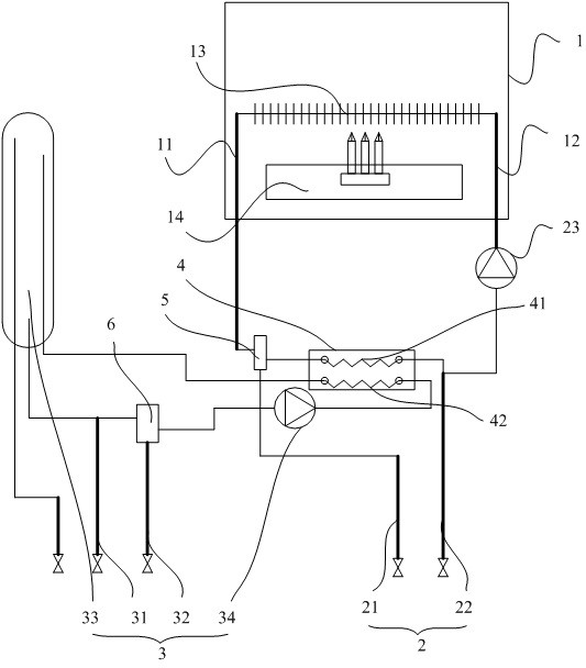
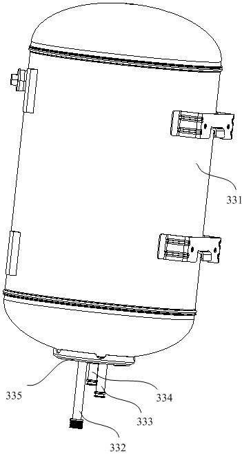
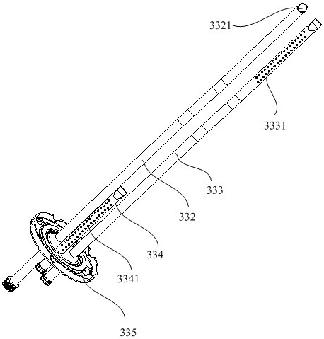
[0029] like Figure 1 - Figure 4 As shown in...


PUM


Abstract

The invention discloses gas heating equipment and a heating hot water supply system. The gas heating equipment is characterized in that a main water outlet and a main water inlet are arranged on gas furnace, a heating water outlet pipe and a heating water return pipe are arranged on a heating assembly, a cold water inlet pipe, a zero-cold water return pipe, a water tank and a water pump are arranged on a hot water supply assembly, a hot water outlet and a circulating water inlet are arranged on the water tank, a first heat exchange flow channel and a second heat exchange flow channel which canexchange heat with each other are arranged on a heat exchanger, the main water outlet is connected with the heating water outlet pipe and the first heat exchange flow channel through a first reversing valve, the heating water return pipe and the first heat exchange flow channel are connected with the main water inlet, the second heat exchange flow channel is connected with the cold water inlet pipe and the zero-cold water return pipe through the second reversing valve, and the second heat exchange flow channel is connected with the circulating water inlet. Water stored in an external water pipe is heated or buffered through the water tank, so that the starting and stopping frequency of the gas furnace is reduced, the fluctuation of the water outlet temperature is reduced, the gas consumption is reduced, and the water use experience of a user is improved.

Description

Technical field [0001] Technical Field The present invention belongs to the stove, a gas heating apparatus in particular, relates to a hot water supply and heating system. Background technique [0002] Currently, gas heating device using gas as an energy source to heat the water heating implemented, and as technology advances, the gas heating device may also have a function of supplying hot water to the user simultaneously. For example: Chinese Patent Application No. 201811537311.6 discloses a zero cold gas boiler system can be achieved on the one hand the heating requirements of the room, on the other hand may be cold and hot water supply zero. However, in actual use, in order to achieve zero cold, you need to outlet pipe in cold water transported by the return pipe to the gas furnace for heat pumps by re-delivered to the outlet pipe. However, since the water stored in the smaller outlet pipe when heated by the combustion gas furnace, a gas furnace affected by the minimum heatin...

Claims


Application Information

Patent Timeline
Patent Type & Authority Applications(China)
IPC IPC(8): F24H1/50F24H9/00F24H9/12F24H9/14F24H9/20
CPCF24H1/50F24H9/144F24H9/2035F24H9/0005F24H9/133
Inventor 石莹曹立国郑涛靳德峰张明
Owner QINGDAO ECONOMIC & TECHN DEV ZONE HAIER WATER HEATER
Learn More