
Method for detecting gas content of oil sample

A detection method and gas content technology, applied in sampling devices, analysis materials, instruments, etc., can solve the problems of low work efficiency, expensive instruments, and only one sample can be detected, and achieve the effect of labor saving and simple operation

Pending Publication Date: 2020-12-04
GUANGDONG POWER GRID CORP ZHAOQING POWER SUPPLY BUREAU
View PDF11 Cites 0 Cited by
  • Summary
  • Abstract
  • Description
  • Claims
  • Application Information

AI Technical Summary

Problems solved by technology

The detection time of the gas chromatography method is too long, including the sample oscillation link and the gas chromatograph detection link. It takes nearly 3 hours to detect a sample, and only one sample can be detected at a time, which is not conducive to rapid detection, and the instrument is expensive; vacuum The accuracy of the degassing method is mainly related to the degree of vacuuming, and the system error is relatively large. Since the vacuum degree of the inner chamber of the test needs to be checked and the oil sample is preheated before each test, the test time is close to one hour, and each time only Can detect one sample, low work efficiency
At present, in order to improve the above situation, there is a Chinese patent with the announcement number CN107063920B and the announcement date of 2019.11.29-a device and method for measuring the gas content in insulating oil. The detection process is simplified, but only one sample can be detected at a time, and the work efficiency is low

Method used


Image

  • Method for detecting gas content of oil sample

Examples


Embodiment 1

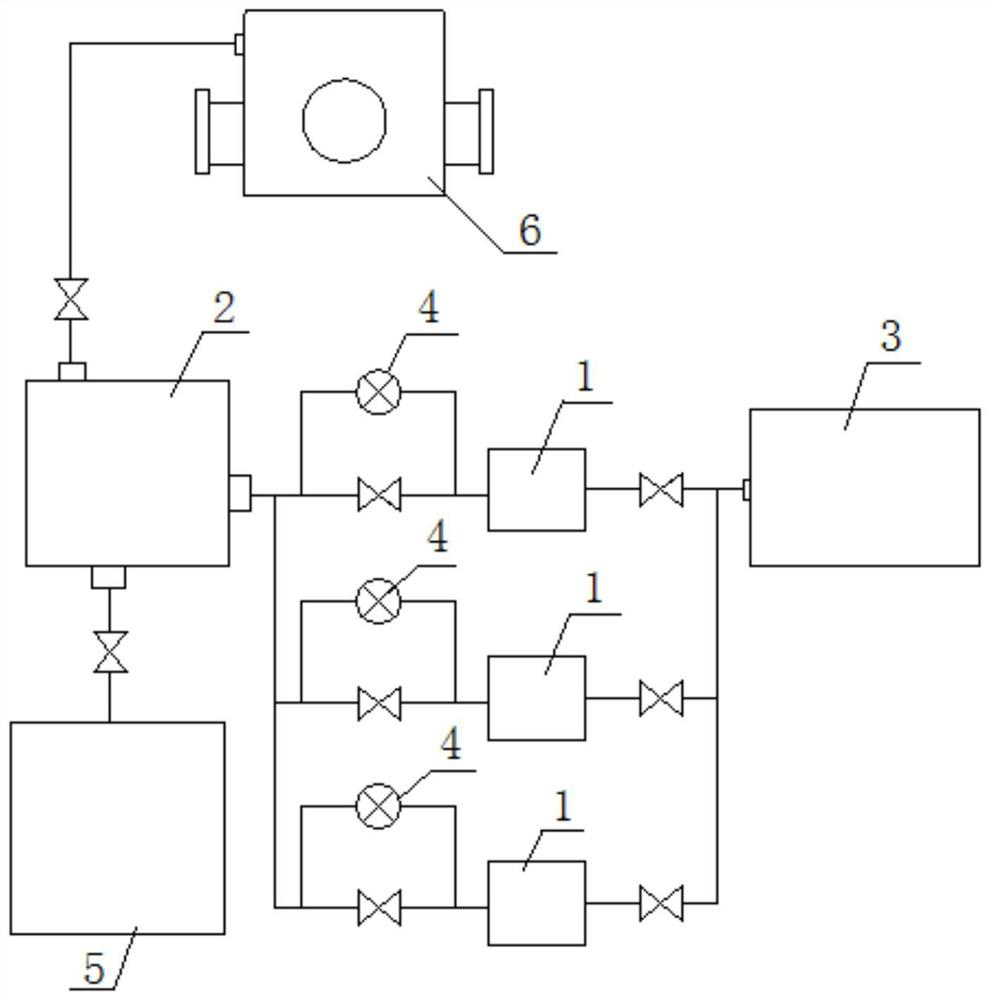
[0028] Such as figure 1 Shown, a kind of oil sample gas content detection method comprises the following steps:

[0029] S1. Preparation equipment: sealed container 1, quantitative sampler 2, vacuum device 3, vacuum degree measuring device 4, waste oil collector 5;

[0030] S2. Equipment connection: the oil valve of the transformer 6 is connected to the oil inlet of the quantitative sampler 2 through the oil pipe, the oil discharge port of the quantitative sampler 2 is connected to the waste oil collector 5 through the oil pipe, and the oil outlet of the quantitative sampler 2 is connected to There are multiple branch pipes, each branch pipe is connected to the oil inlet of a vessel 1 respectively, and the air vent of each vessel 1 is connected to the same vacuum device 3 through the oil pipe, and valves are installed on each oil pipe and branch pipe; Both sides of the valve of each branch pipeline are connected with a vacuum measuring device 4;

[0031] S3. Sampling: before...


PUM


Abstract

The invention discloses a method for detecting the gas content of an oil sample. Sealed vessels, a quantitative sampler, a vacuumizing device, vacuum degree measuring devices and a waste oil collectorare included. The oil taking valve of a transformer is connected with the oil inlet of the quantitative sampler through an oil pipe, the oil outlet of the quantitative sampler is communicated with the waste oil collector through an oil pipe, the oil outlet of the quantitative sampler is connected with a plurality of branch pipelines, and each branch pipeline is correspondingly communicated with the oil inlet of each vessel. The air vent of each vessel is communicated with the same vacuumizing device through an oil pipe, and valves are mounted on each oil pipe and each branch pipeline; the twosides of the valve of each branch pipeline are each connected with one vacuum degree measuring device; and related valves are controlled to perform sampling and vacuumizing in sequence, and the gas content of the oil sample is detected. According to the detection method, multiple samples of the transformer oil can be detected on site at the same time, the detection speed can be increased, the detection cost is reduced, and labor is saved.

Description

technical field [0001] The invention belongs to the technical field of electric power testing, and in particular relates to a method for detecting the gas content of an oil sample. Background technique [0002] The gas content in oil refers to the volume percentage of dissolved gas in transformer oil. According to professional statistics, the newly put into operation transformer oil samples in the gas content experiment in oil accounted for more than 85% of the total tested samples, that is, most of them were The air content detection is carried out on the newly put into operation transformer oil, and the main component of the air content in the newly put into operation transformer oil is air (other components have not yet been produced), therefore, a rapid detection method for the newly put into operation transformer oil A method of testing the air content in the oil becomes extremely important. [0003] The current detection methods include gas chromatography and vacuum d...

Claims


Application Information

Patent Timeline
Patent Type & Authority Applications(China)
IPC IPC(8): G01N7/14G01N1/10
CPCG01N7/14G01N1/10
Inventor 朱琪吴建光陈威雄陈妙妹廖丽霞冼锋胡家昊
Owner GUANGDONG POWER GRID CORP ZHAOQING POWER SUPPLY BUREAU
Learn More