Electric connector

A technology for electrical connectors and contact parts, which is applied in the direction of connections, circuits, and parts of connection devices. The effect of service life

Active Publication Date: 2020-12-04
DEYI PRECISION ELECTRONIC IND CO LTD PANYU
View PDF4 Cites 0 Cited by
  • Summary
  • Abstract
  • Description
  • Claims
  • Application Information

AI Technical Summary

Problems solved by technology

[0003] However, since the width of the ground terminal in the left-right direction is relatively small, and the first contact portion is aligned with the second contact portion, the first contact portion and the second contact portion are aligned in the left-right direction. The distance above is relatively small, so that the thickness of the punch punching the gap between the first contact part and the second contact part in the left and right direction is smaller than that used to form the first contact part and the second contact part. The thickness of the metal sheet of the part makes the punch prone to breakage when forming the first contact part and the second contact part
In addition, when the shielding shell deviates to the right due to factors such as external vibrations, the first contact portion abuts against the mating portion of the ground terminal to the right to generate a relatively large positive force. Due to factors such as external vibrations shifting to the left, the second contact portion abuts against the mating portion of the ground terminal to the left to generate a relatively large positive force, resulting in a positive force on the mating portion of the ground terminal. The axial force changes greatly before and after the deflection of the shielding shell. Excessive positive force makes the first contact part and the second contact part easy to fatigue, resulting in that when the shielding shell is not deflected In the usual use state, the tired first contact part and the second contact part cannot ensure the stable contact of the ground terminal, which leads to the inability of the shielding shell to achieve stable grounding through the ground terminal, which affects the electrical connector. High frequency performance, unable to meet higher requirements

Method used


Image

  • Electric connector
  • Electric connector
  • Electric connector

Examples


Embodiment Construction

[0058] In order to facilitate a better understanding of the purpose, structure, features, and effects of the present invention, the present invention will now be further described in conjunction with the accompanying drawings and specific embodiments.

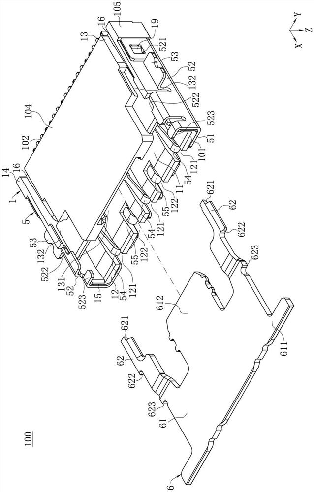
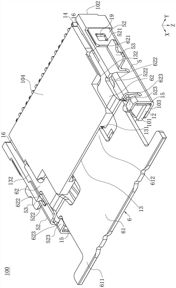
[0059] Such as figure 1 , Figure 4 and Image 6 As shown, the electrical connector 100 of the present invention defines an up-down direction Z, a front-back direction X and a left-right direction Y perpendicular to the up-down direction Z and perpendicular to each other.

[0060] Such as figure 1 , Image 6 and Figure 10 As shown, the electrical connector 100 of the present invention is used for docking with a mating member 200, the electrical connector 100 is installed downward on a circuit board 300, and the mating member 200 is inserted backward into the electrical connector 100 and the two form an electrical connection.

[0061] Such as figure 1 , Figure 4 and Image 6 As shown, the electrical connector 100 has ...


PUM


Abstract

The invention discloses an electric connector. The electric connector comprises an insulating body; a plurality of terminals are arranged on the insulating body and comprise two signal terminal pairsand two grounding terminals positioned between the two signal terminal pairs; the metal shell covers the insulation body and comprises a neck portion extending backwards from the top plate, a first elastic arm, a second elastic arm and a third elastic arm; the first elastic arm, the second elastic arm and the third elastic arm extend backwards from the neck portion; the first elastic arm and the second elastic arm are respectively provided with a rightward first contact portion, and the second elastic arm and the third elastic arm are respectively provided with a leftward second contact portion. The first contact portion of the first elastic arm and the second contact portion of the second elastic arm are staggered, the first contact portion of the second elastic arm and the second contactportion of the third elastic arm are staggered, when the neck portion deviates rightwards, the first contact portion of the first elastic arm abuts against one grounding terminal rightwards, and thefirst contact portion of the second elastic arm abuts against the other grounding terminal rightwards. When the neck portion deviates leftwards, the second contact portion of the second elastic arm abuts against one grounding terminal leftwards, and the second contact portion of the third elastic arm abuts against the other grounding terminal leftwards.

Description

【Technical field】 [0001] The invention relates to an electrical connector, in particular to an electrical connector with improved high-frequency performance. 【Background technique】 [0002] An existing electrical connector is used to connect a pair of mating components. The electrical connector has an insulating body, a plurality of terminals accommodated in the insulating body, and a shielding shell covering the insulating body. body, the top end of the insulating body is recessed toward the bottom end to form a docking cavity for accommodating the docking element. The plurality of terminals are arranged in two rows on both sides of the docking cavity, and each row of terminals includes a plurality of signal terminals and a plurality of ground terminals arranged in the left and right directions, wherein the ground terminals are located on two sides of the docking chamber. Between the signal terminals, each of the ground terminals is provided with a welding portion, and a m...

Claims


Application Information

Patent Timeline
Patent Type & Authority Applications(China)
IPC IPC(8): H01R13/02H01R13/46H01R13/646H01R13/652H01R12/72
CPCH01R13/652H01R13/646H01R13/46H01R13/02H01R12/722H01R13/6471H01R13/6594H01R12/89H01R12/79H01R13/05H01R13/502H01R13/6585
Inventor 程伟进
Owner DEYI PRECISION ELECTRONIC IND CO LTD PANYU
Why Eureka
Try Eureka