[0019] The following will clearly and completely describe the technical solutions in the embodiments of the present invention with reference to the accompanying drawings in the embodiments of the present invention. Obviously, the described embodiments are only some, not all, embodiments of the present invention. Based on the embodiments of the present invention, all other embodiments obtained by persons of ordinary skill in the art without making creative efforts belong to the protection scope of the present invention.
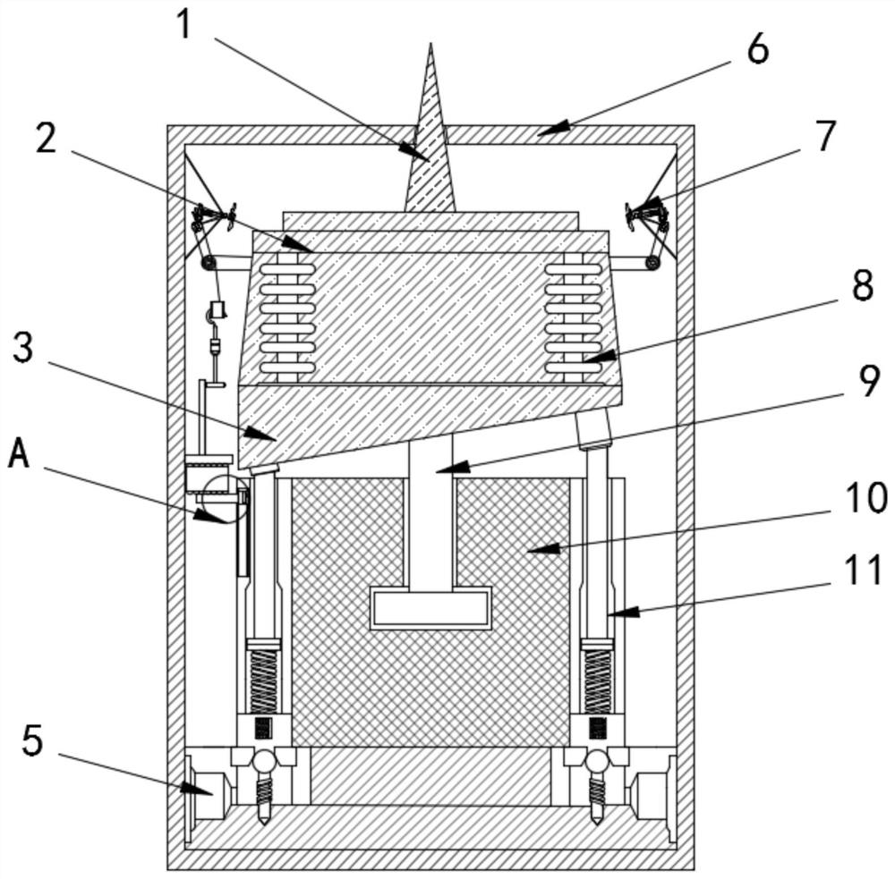
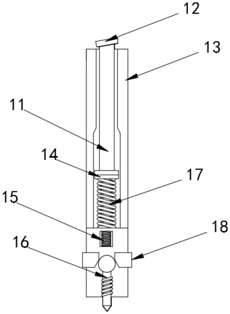
[0020] see Figure 1-5 , a 5G signal base station with a current protection function, comprising a box body 6, a support seat 10 is installed at the inner bottom of the box body 6, and a distributor 5 is installed on the left and right sides of the inner bottom end of the box body 6, and the support seat 10 Mounting rods 13 are fixedly connected to the left and right sides of the support base 10, and a movable connecting rod 9 is movably connected to the middle position inside the support seat 10, and a guide rod 16 is movably connected to the lower end of the mounting rod 13, and the lower end of the mounting rod 13 is located at the guide rod Limiting blocks 18 are installed on the left and right sides of 16, and the bottom end of the installation rod 13 is embedded with an iron core 15, and the inside of the installation rod 13 is slidably connected with a push rod 11 above the iron core 15, and the iron core The surface of 15 is wound with a coil, the lower surface of the top block 14 is embedded with a magnetic block, the lower surface of the push rod 11 is fixedly connected with the top block 14, and the upper surface of the push rod 11 is fixedly connected with the baffle plate 12, the top block 14 The lower surface is fixedly connected with a connecting spring 17, and the left side surface of the left mounting bar 13 is slidably connected with a baffle plate 12, and the left side surface of the left side mounting bar 13 is provided with a chute, and the right end of the baffle plate 12 is slidably connected to the sliding door. Inside the groove, the top of the baffle plate 12 is provided with an air bag 4, and the right side of the baffle plate 12 is provided with a first connecting gear 21, the front and rear ends of the air bag 4 are fixedly connected with the casing 6, and the lower end of the threaded plate 26 is fixedly connected with Pressing plate fits with the upper surface of air bag 4, and the top of air bag 4 is provided with threaded plate 26, and the right side surface of threaded plate 26 is meshed with mounting seat 2, and the upper end of tooth plate 23 is movably connected with rotating shaft 25, and rotating shaft 25 A support block 24 is provided above, and a runner 19 is arranged above the support block 24, and a second pulley is installed at the middle position of the rear surface of the runner 19, and the second pulley is connected with the pulley 20 and the support block 24 respectively by a belt rope. Belt pulley 20 is arranged on the top of runner 19, and the upper surface of belt pulley 20 is connected with the lower end of second connection gear 22 through belt pulley group, and is fixedly connected with connecting shaft between the first connection gear 21 and air fan 7, and the top of belt pulley 20 is arranged There is a second connecting gear 22, the upper surface of the second connecting gear 22 is meshed with the first connecting gear 21, the end of the first connecting gear 21 is fixedly connected with the air fan 7, and the left and right sides of the upper surface of the adjustment dial 3 are movably connected There is a resistance block 8 , and a mounting base 2 is arranged above the adjusting dial 3 , and a signal transmitter 1 is installed in the middle of the upper surface of the mounting base 2 .
[0021] When in use, when the current of the device is too high to cause high temperature inside the box body 6, the airbag 4 on the left side of the box body absorbs a large amount of heat, expands when heated, and becomes full from the original flat state. The airbag 4 When the contact area is full, the threaded plate 26 is moved upwards, and the threaded plate 26 drives the tooth plate 23 to rotate, and the rotating shaft 25 is driven to rotate, and the rotating shaft 25 rotates to drive the supporting block 24 to rotate. The meshed rotary drive tightens the wire rope, makes the runner 19 rotate, and then drives the second connecting gear 22 to rotate through the pulley set, and the first connecting gear 21 meshed with it rotates, and finally drives the air fan 7 to rotate, and the air fan 7 rotates to extract Moisture in the equipment, and the moisture is discharged through the holes opened on the box body 6, which ensures the dryness inside the equipment, prevents the internal components of the box body 6 from being oxidized and corroded by the humid air, and solves the problem that the components cannot work due to the humid air The problem.
[0022] Simultaneously, when the airbag 4 is heated and expanded, it squeezes the baffle plate 12, and the conductive rod on the right side of the baffle plate 12 slides down to fit the bottom end of the variable resistor 21, and the external power supply supplies power to the iron core 15, and the iron core The magnetic induction intensity of 15 increases, and the upper end of the iron core 15 is the same as the magnetic pole of the lower end of the magnetic block, pushes the ejector rod 11 upwards, the guide rod 16 drives upwards, and pushes against the adjusting dial 3 on it, and a metal plate is arranged above the ejector rod 11. Seat, the outer frame of the adjusting dial 3 is provided with an uneven straight line, the straight line is provided with a texture matching the metal seat, the metal seat pushes against the adjusting dial 3 above, and the driving force of the metal seat is greater than that of the adjusting dial 3, when When the push rod 11 at the left end is pushed upwards, the lowest point on the left end of the adjustment dial 3 turns to the right end, and the distributor 5 transfers the current from the left end to the right end. , the overall circuit is a parallel circuit, the current is divided equally into the ejector rods 11 on both sides, and then adjusted by the distributor 2, the overall equipment operates normally, which increases the stability of the internal current of the equipment and protects the signal transmitter 1.
[0023] Although the embodiments of the present invention have been shown and described, those skilled in the art can understand that various changes, modifications and substitutions can be made to these embodiments without departing from the principle and spirit of the present invention. and modifications, the scope of the invention is defined by the appended claims and their equivalents.