High-reliability household vegetable pulverizer
A reliable, pulverizer technology, used in household machinery, household appliances, applications, etc. for filtering food, which can solve the problems of food residue splashing on the inner wall, lowering, and inability to fully pulverize.
- Summary
- Abstract
- Description
- Claims
- Application Information
AI Technical Summary
Problems solved by technology
Method used
Image

Examples
Embodiment Construction
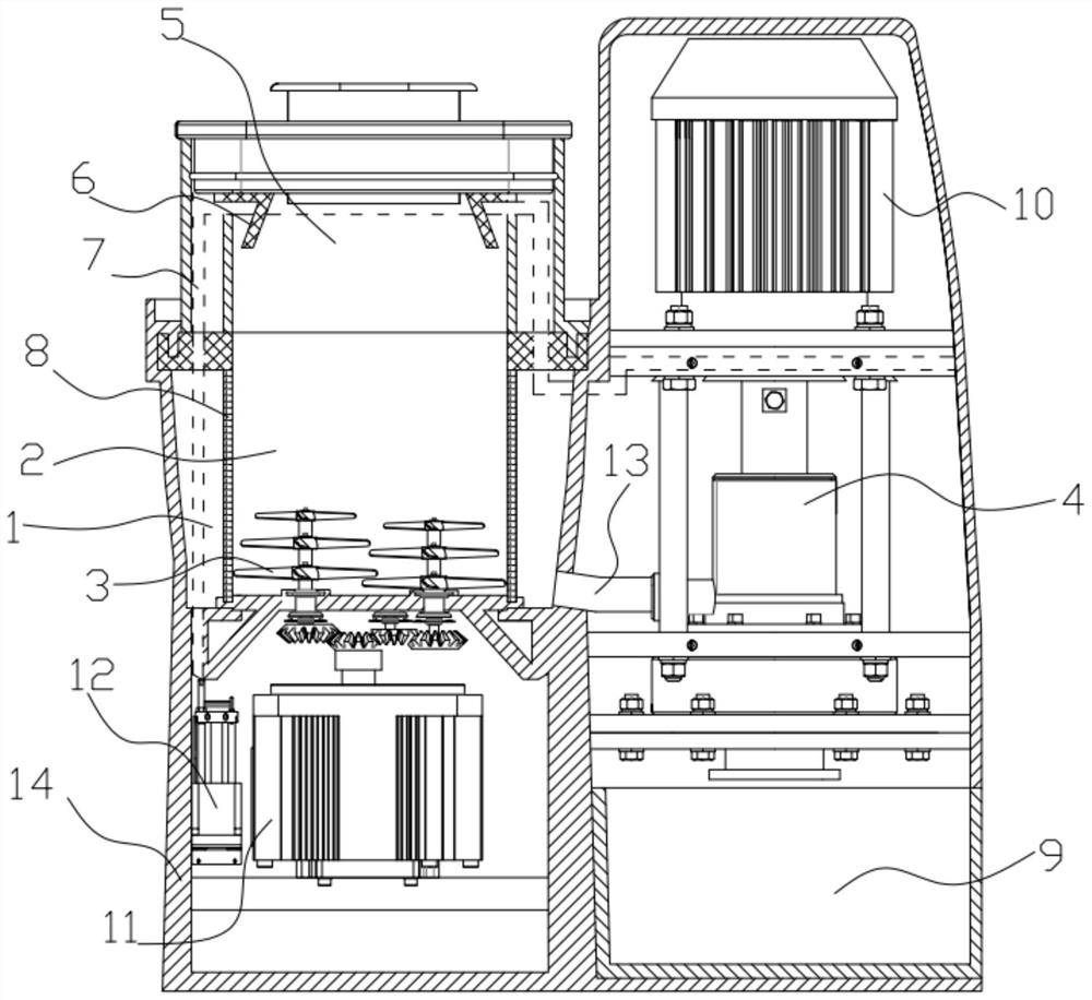
[0028] see figure 1 , in an embodiment of the present invention, a high-reliability household vegetable shredder includes a body 14, a crushing chamber 2, a crushing cutter head 3, and an emulsifying assembly 4, wherein the body 14 is two cylinders connected together on the left and right The left side of the cavity is a crushing cavity 2. A detachable feed cover 5 is arranged above the crushing cavity 2. There are two groups of crushing cutter heads 3 with opposite rotation directions at the bottom of the crushing cavity 2. The surrounding of the crushing chamber 2 is a detachable filter screen 8, the juice chamber 1 is between the filter screen 8 and the body 14, and the lower end of the juice chamber 1 is connected with the emulsification component 4 arranged in the right side chamber of the body 14 through a pipe 13 ;
[0029] The emulsification component 4 can suck the juice in the juice chamber 1 and break the fibers, cell walls, etc. therein;
[0030] A extractable ve...
PUM
 Abstract
Description
Claims
Application Information
PatSnap Eureka turns technology decisions into work you can execute. Powered by our Innovation Knowledge Graph, it runs expert workflows across engineering, life sciences, materials and intellectual property. Get your review-ready output in minutes.


