Hardware strip bending device

A bending device and hardware technology, which is applied in the field of hardware processing, can solve the problems of inability to perform spiral bending and small damage rate, and achieve good results and ensure precision

Inactive Publication Date: 2020-12-08
马国庆
View PDF8 Cites 0 Cited by
  • Summary
  • Abstract
  • Description
  • Claims
  • Application Information

AI Technical Summary

Problems solved by technology

The device achieves good bending effect, does not affect the use of metal bars, and has a small damage rate. Because of its simple operation, reasonable design, and strong applicability, it has obvious advantages in processing a large number of metal bars. However, the device only It can be bent at a certain angle, but cannot be bent spirally, so the device needs to be improved

Method used


Image

  • Hardware strip bending device
  • Hardware strip bending device
  • Hardware strip bending device

Examples


Embodiment 1

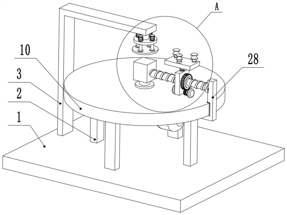
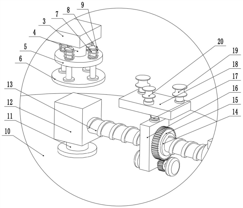
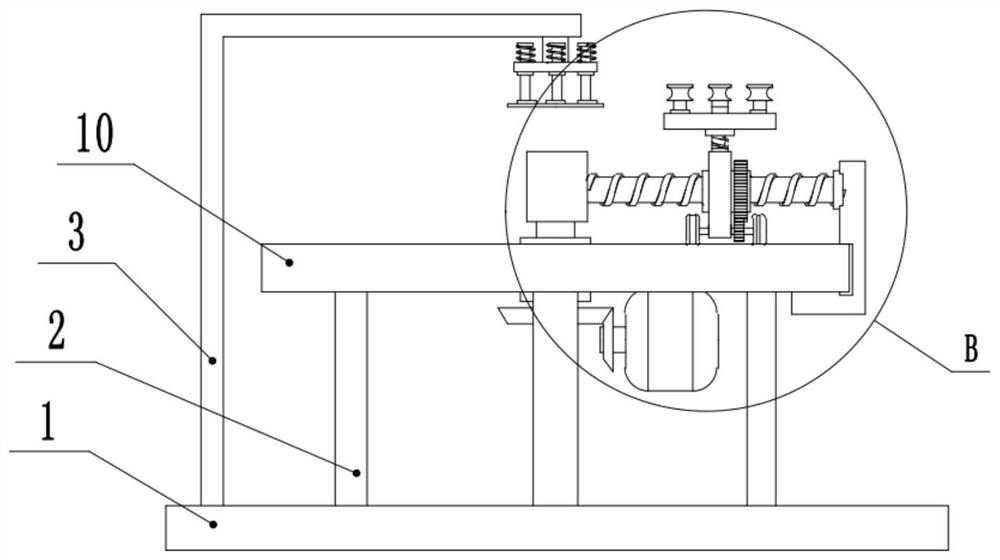
[0023] see Figure 1-4 , a metal bar bending device, comprising a base plate 1, a fixed frame 3 is provided on the left side of the upper surface of the base plate 1, a fixed rod 4 is provided at the right end of the fixed frame 3, and a fixed block 5 is provided at the bottom of the fixed rod 4, and the fixed block The outer side of 5 slides and connects guide rod 7, and the lower end of guide rod 7 is provided with movable plate 6, and the upper end of guide rod 7 is provided with stop block 9, is provided with spring 8 between stop block 9 and fixed block 5, and spring 8 sets On the outside of the guide rod 7, the spring 8 is limited by the guide rod 7. The right side of the upper surface of the base plate 1 is provided with a support column 2, and the upper end of the support column 2 is provided with a workbench 10 for working. The middle part of the table 10 is rotatably connected to the middle part of the rotating shaft 11, the top of the rotating shaft 11 is provided w...

Embodiment 2

[0026] see figure 1 , the other content of this embodiment is the same as that of Embodiment 1, except that the right end of the screw rod 13 is rotatably connected to the upper part of the block 28, and the lower part of the block 28 is slidably connected to the side of the workbench 10. In order to maintain the force balance of the screw mandrel 13, a block 28 is provided at the right end of the screw mandrel 13, and a part of the force of the screw mandrel 13 is transmitted to the workbench 10 through the block 28, thereby reducing the requirement for the rigidity of the screw mandrel 13. At the same time, the workbench 10 needs to be designed as a circle, and the friction between the block 20 and the workbench 10 needs to be reduced as much as possible. A bush is arranged between them, and the friction force is reduced through the bush, so that the screw rod 13 can better rotate around the rotating shaft 11 .

[0027]During the implementation of the present invention, the...


PUM


Abstract

The invention relates to the technical field of hardware processing, and discloses a hardware strip bending device. The hardware strip bending device comprises a bottom plate, wherein a fixing frame is arranged on the left side of the upper surface of the bottom plate; a fixing rod is arranged at the right end of the fixing frame; a fixing block is arranged at the lower part of the fixing rod; a supporting column is arranged on the right side of the upper surface of the bottom plate; a workbench is arranged at the upper end of the supporting column; the middle of the workbench is rotationallyconnected with the middle of a rotating shaft; the upper part of the rotating shaft is provided with a rotating block; the left side of the rotating block is provided with a lead screw; the middle ofthe lead screw is connected with a driving nut in a threaded mode; the left side of the driving nut is rotationally connected with the middle of a fixing plate; the lower part of the fixing plate is rotationally connected with a rotating rod; and the left end and the right end of the rotating rod are provided with driving wheels. According to the hardware strip bending device, the rotating shaft is arranged to drive the fixing plate to rotate, and in the rotating process, the driving nut moves along the lead screw, so that the fixing plate finally moves along the track of a spiral involute, and consequently, a hardware strip is bent.

Description

technical field [0001] The invention relates to the technical field of hardware processing, in particular to a metal bar bending device. Background technique [0002] Hardware: traditional hardware products, also known as "hardware". Refers to the five metals of gold, silver, copper, iron, and tin. After manual processing, it can be made into works of art or metal devices such as knives and swords. Hardware in modern society is more extensive, such as hardware tools, hardware parts, daily hardware, construction hardware and security supplies. Some hardware, such as springs, require spiral bending during processing, and bending straight components is also a common metal processing operation. [0003] Chinese patent (notification number: CN206083494U) discloses a metal bar bending device, including an L-shaped frame, a bottom plate, a first slide rail, a first slider, a fixed plate, a magnet block, a pressure plate, an L-shaped connecting rod, a second The second slide blo...

Claims


Application Information

Patent Timeline
Patent Type & Authority Applications(China)
IPC IPC(8): B21D11/06B21D11/22
CPCB21D11/06B21D11/22
Inventor 马国庆
Owner 马国庆
Why Eureka
Try Eureka