
Machining device for side grooving and end face machining of honeycomb plate and double-side machining equipment of honeycomb plate
A processing device and end face processing technology, which is applied to other manufacturing equipment/tools, manufacturing tools, etc., can solve the problems of saw blades easily scratching panels, unstable processing quality, and low efficiency, so as to broaden the scope of application and avoid secondary The effect of grinding and reducing costs
- Summary
- Abstract
- Description
- Claims
- Application Information
AI Technical Summary
Problems solved by technology
Method used
Image

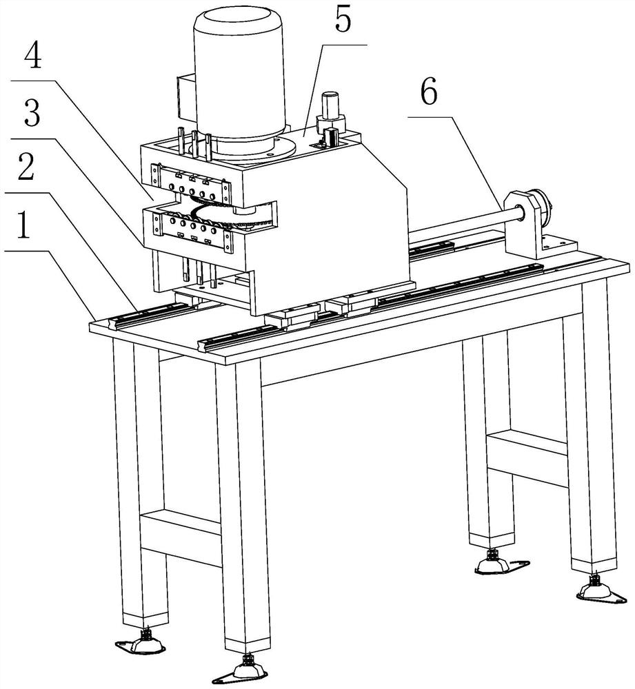
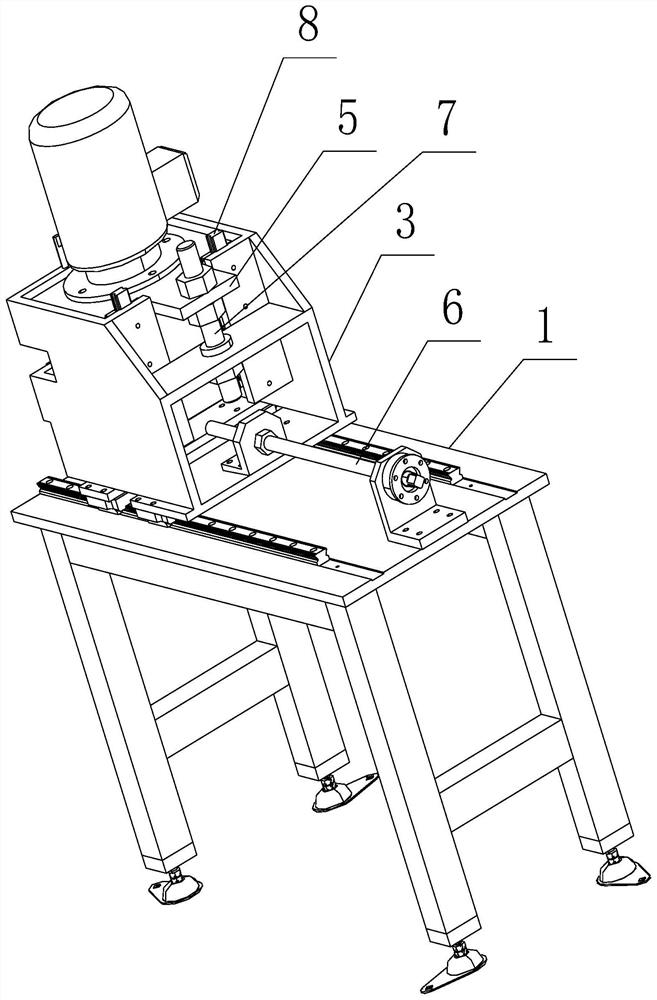
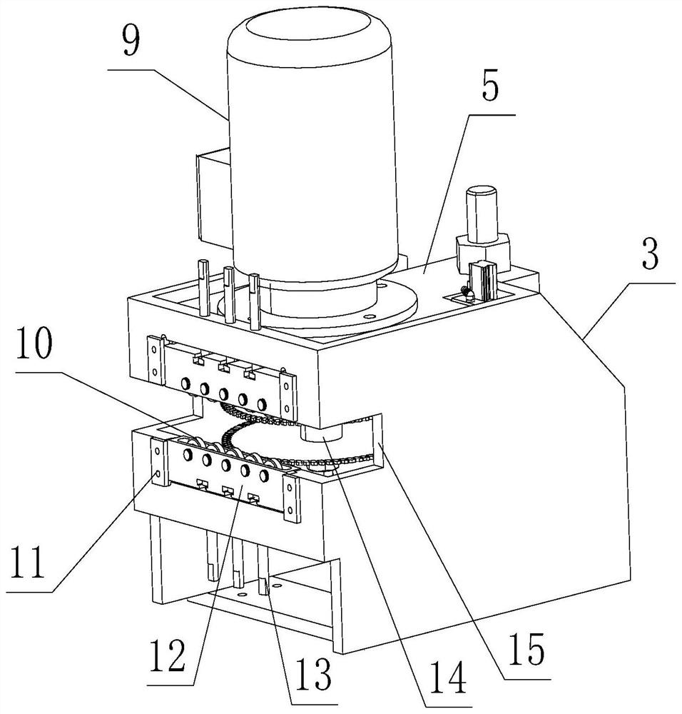
Examples
Embodiment Construction
[0033] Embodiments of the present invention are described below through specific examples, and those skilled in the art can easily understand other advantages and effects of the present invention from the content disclosed in this specification. The present invention can also be implemented or applied through other different specific implementation modes, and various modifications or changes can be made to the details in this specification based on different viewpoints and applications without departing from the spirit of the present invention. It should be noted that the diagrams provided in the following embodiments are only schematically illustrating the basic concept of the present invention, and the following embodiments and the features in the embodiments can be combined with each other in the case of no conflict.
[0034] Wherein, the accompanying drawings are for illustrative purposes only, and represent only schematic diagrams, rather than physical drawings, and should...
PUM
 Abstract
Description
Claims
Application Information