Plastic injection molding cutting platform facilitating material overturning

A cutting platform and plastic technology, applied in metal processing and other directions, can solve the problems of affecting cutting quality, inability to flip plastic, and greatly affecting cutting accuracy, so as to improve convenience, ensure convenience, and prevent pollution of the workshop environment.

Inactive Publication Date: 2020-12-08
应嘉迪
View PDF8 Cites 1 Cited by
  • Summary
  • Abstract
  • Description
  • Claims
  • Application Information

AI Technical Summary

Problems solved by technology

However, the existing cutting platform equipment cannot directly flip the plastic, but can only perform secondary positioning and clamping, and the plastic flip cutting process has been completed
This processing method requires two positioning and clamping of the plastic, so that the clamping accuracy has a great influence on the cutting accuracy of the plastic and directly affects the cutting quality

Method used


Image

  • Plastic injection molding cutting platform facilitating material overturning
  • Plastic injection molding cutting platform facilitating material overturning
  • Plastic injection molding cutting platform facilitating material overturning

Examples


Embodiment 1

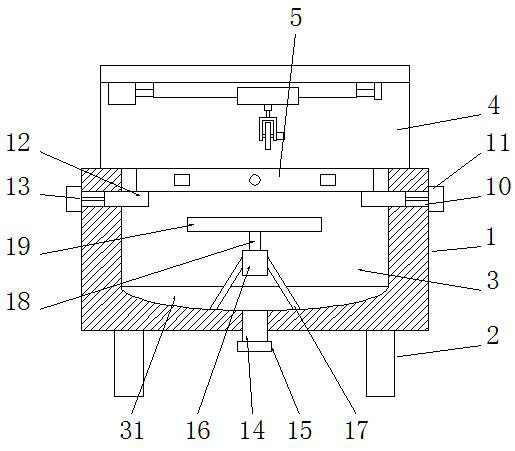
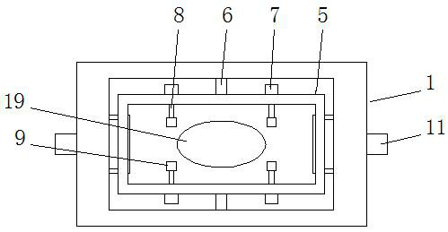
[0031] See Figure 1-2 , a plastic injection molding cutting platform that is convenient for turning over materials, including a machine platform 1, a cutting cavity 3 is embedded in the top end of the machine platform 1, and the bottom end of the cutting cavity 3 is connected to a diversion cavity 31, and the machine platform The edge of the bottom end of 1 is evenly provided with several supporting legs 2, and the inner cavity of the cutting chamber 3 is provided with an overturning frame 5, and the overturning frame 5 is a rectangular ring frame, and the front and rear ends of the overturning frame 5 are rotatably connected to the On the inner cavity wall of the cutting chamber 3, the top surface of the turning frame 5 is flush with the top surface of the machine table 1, and the front and rear ends of the turning frame 5 are uniformly provided with a plurality of first electric telescopic devices 7, and the first electric telescopic The movable end of the first telescopic ...

Embodiment 2

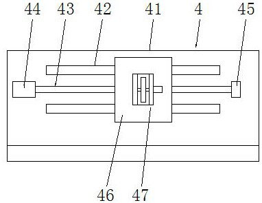
[0036] See Figure 3-4 The difference from Embodiment 1 is that the cutting mechanism 4 includes a vertical plate 41, the vertical plate 41 is an L-shaped structure, and the inner cavity top wall of the vertical plate 41 is symmetrically provided with guide rails 42 front and rear, and the guide rails 42 are T-shaped guide rail, a lead screw 43 is arranged between the two guide rails 42, and the relationship between the guide rail 42 and the lead screw 43 is parallel to each other. One end of the lead screw 43 is connected to the feed motor 44 in rotation, and the lead screw 43 The other end is rotatably connected to the vertical plate 41 through the bearing seat 45, the feed motor 44 is fixedly mounted on the vertical plate 41, the leading screw 43 is sleeved with a moving seat 46 matched with the guide rail 42, and the moving seat 46 The bottom end of the cutting tool assembly 47 is fixedly installed, and the feed motor 44 drives the lead screw 43 to rotate positively and ne...

Embodiment 3

[0039] See Figure 5 , and the difference from embodiment 2 is that: the inner cavity side wall of the vertical plate 41 is provided with a water spraying part 20 matched with the overturn frame 5, and the water spraying part 20 is evenly provided with a number of nozzles 21, so The top of the vertical plate 41 is fixedly connected to the water tank 23, and the water tank 23 is connected to the water spray member 20 through the water pipe 22. The water pump 27 is installed on the water pipe 22, and the water in the water tank 23 is extracted by the water pump 27, so that the water flows along the water pipe. 22 into the water spray member 20, and finally spray the water flow through the nozzle 21, and then use the water flow to spray on the turning frame 5, and use the water flow to clean the cutting disc knife 474, which can effectively prevent the cutting plastic chips from splashing, thereby ensuring the cutting of plastic products. environmental protection;

[0040] The t...


PUM


Abstract

The invention discloses a plastic injection molding cutting platform facilitating material overturning. The plastic injection molding cutting platform comprises a machine table, wherein a cutting cavity is embedded into the top end of the machine table; the bottom end of the cutting cavity is connected to a flow guide cavity in a penetrating mode; a plurality of supporting legs are uniformly arranged on the edge of the bottom end of the machine table; an overturning frame is arranged in an inner cavity of the cutting cavity; the front end and the rear end of the overturning frame are rotatablyconnected to the inner cavity wall of the cutting cavity through rotating shafts; a plurality of first electric telescopic devices are uniformly arranged at the front end and the rear end of the overturning frame; and the movable ends of first telescopic rods on the first electric telescopic devices penetrate through the side wall of the overturning frame and are fixedly connected to clamps. Whenthe plastic injection molding cutting platform is used, a to-be-cut plastic product is placed in the inner cavity of the overturning frame, the first electric telescopic devices are matched with thefirst telescopic rods to eject the clamp out, and the plastic product is clamped through the clamps; and the plastic product can be overturned by directly overturning the overturning frame, so that the convenience for overturning of the plastic product is greatly improved, and the influence of the clamping precision on the cutting precision of the plastic can be effectively avoided.

Description

technical field [0001] The invention relates to the technical field of cutting platform equipment, in particular to a plastic injection molding cutting platform which is convenient for overturning materials. Background technique [0002] Injection molding is a method of producing shapes for industrial products. Products usually use rubber injection molding and plastic injection molding. Injection molding can also be divided into injection molding molding method and die casting method. Plastic injection molding is a method of plastic products. The molten plastic is injected into the mold of the plastic product under pressure, and cooled and formed to obtain various plastic parts. There are mechanical injection molding machines specially designed for injection molding. The most commonly used plastic today is polystyrene. [0003] Plastic needs to be cut during the production process, and the existing plastic cutting needs the help of cutting platform equipment. Makes plas...

Claims


Application Information

Patent Timeline
IPC IPC(8): B26D1/18B26D5/08B26D7/08B26D7/02B26D7/01B26D7/26B26D7/00B26D7/18
CPCB26D1/18B26D5/086B26D7/00B26D7/01B26D7/02B26D7/088B26D7/18B26D7/2621B26D7/2635
Inventor 应嘉迪
Owner 应嘉迪
Why Eureka
Try Eureka