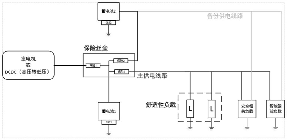
Vehicle power supply system and power supply control method
A power supply system and vehicle technology, which is applied to vehicle components, circuits or fluid pipelines, transportation and packaging, etc., can solve the problems of shortened battery life, insufficient life, high DCDC cost, etc., and achieve the effect of meeting power supply needs
- Summary
- Abstract
- Description
- Claims
- Application Information
AI Technical Summary
Problems solved by technology
Method used
Image
Examples
Embodiment 1
[0027] Figure 4 It is a schematic structural diagram of a vehicle power supply system provided by Embodiment 1 of the present invention. This embodiment is applicable to the power supply of intelligent driving vehicles.
[0028] Such as Figure 4 As shown, a vehicle power supply system provided by Embodiment 1 of the present invention includes: a first power supply module 11, a second power supply module 12, a control module 13, and a power switch module 14; wherein, the second power supply module 12 passes through the power switch module 14 is externally connected to the load 15, the first power supply module 11 is externally connected to the load 15, and the control module 13 is respectively connected to the load 15 and the power switch module 14.
[0029] The first power supply module 11 is used to supply power to the load 15 .
[0030] The control module 13 is configured to detect the power supply status of the load 15 by the first power supply module 11 ; generate a sw...
Embodiment 2
[0043] On the basis of the foregoing embodiments, the embodiments of the present application further optimize the foregoing vehicle power supply system.
[0044] Figure 5 It is a schematic structural diagram of a vehicle power supply system provided by Embodiment 2 of the present invention. Such as Figure 5 As shown, the power switch module 14 of the vehicle power supply system in this embodiment includes a first switch 141 , and the second power supply module 12 is externally connected to the load 15 through the first switch 141 in the power switch module 14 .
[0045] The control module 13 is specifically configured to generate a close switch signal and send it to the power switch module 14 when the first power supply module 11 fails to supply power to the load 15 normally.
[0046] The power switch module 14 is specifically configured to determine that the first switch 141 is closed based on the closed switch signal.
[0047] The second power supply module 12 is config...
Embodiment 3
[0073] Figure 6 It is a flow chart of a power supply control method provided in Embodiment 3 of the present invention. The method is executed by the vehicle power supply system provided in the above embodiment, including:
[0074] S110. Detect, through the control module, that the first power supply module supplies power to the load.
[0075] S120. The control module generates a switch signal based on the load power supply situation and sends it to the power switch module.
[0076] S130. Determine, by the power switch module, a switch state of the power switch module based on the received switch signal.
[0077] S140. Use the second power supply module to supply power to the load based on the switch state of the power switch module.
[0078] Wherein, the power switch module includes a first switch, and the second power supply module is externally connected to a load through the first switch in the power switch module.
[0079] When the first power supply module fails to su...
PUM
 Abstract
Description
Claims
Application Information
 - R&D
- Intellectual Property
- Life Sciences
- Materials
- Tech Scout
- Unparalleled Data Quality
- Higher Quality Content
- 60% Fewer Hallucinations
Browse by: Latest US Patents, China's latest patents, Technical Efficacy Thesaurus, Application Domain, Technology Topic, Popular Technical Reports.
© 2025 PatSnap. All rights reserved.Legal|Privacy policy|Modern Slavery Act Transparency Statement|Sitemap|About US| Contact US: help@patsnap.com


