Driver state detection device

A driver status and detection device technology, which is applied in the directions of driver input parameters, control devices, transportation and packaging, etc., can solve the problem of lower detection accuracy of line of sight direction, inability to detect the direction of the driver's line of sight to the side rearview mirror with high precision, etc. problems, to achieve the effect of improving wiring efficiency, easy installation space, and improving detection accuracy

Pending Publication Date: 2020-12-08
HONDA MOTOR CO LTD
View PDF1 Cites 0 Cited by
  • Summary
  • Abstract
  • Description
  • Claims
  • Application Information

AI Technical Summary

Problems solved by technology

[0003] However, in the conventional driver state detection device, when the driver's line of sight is directed toward a wide-angle direction that forms a relatively large angle with respect to the driver's point of view in a plan view, the ...

Method used


Image

  • Driver state detection device
  • Driver state detection device
  • Driver state detection device

Examples


no. 1 approach

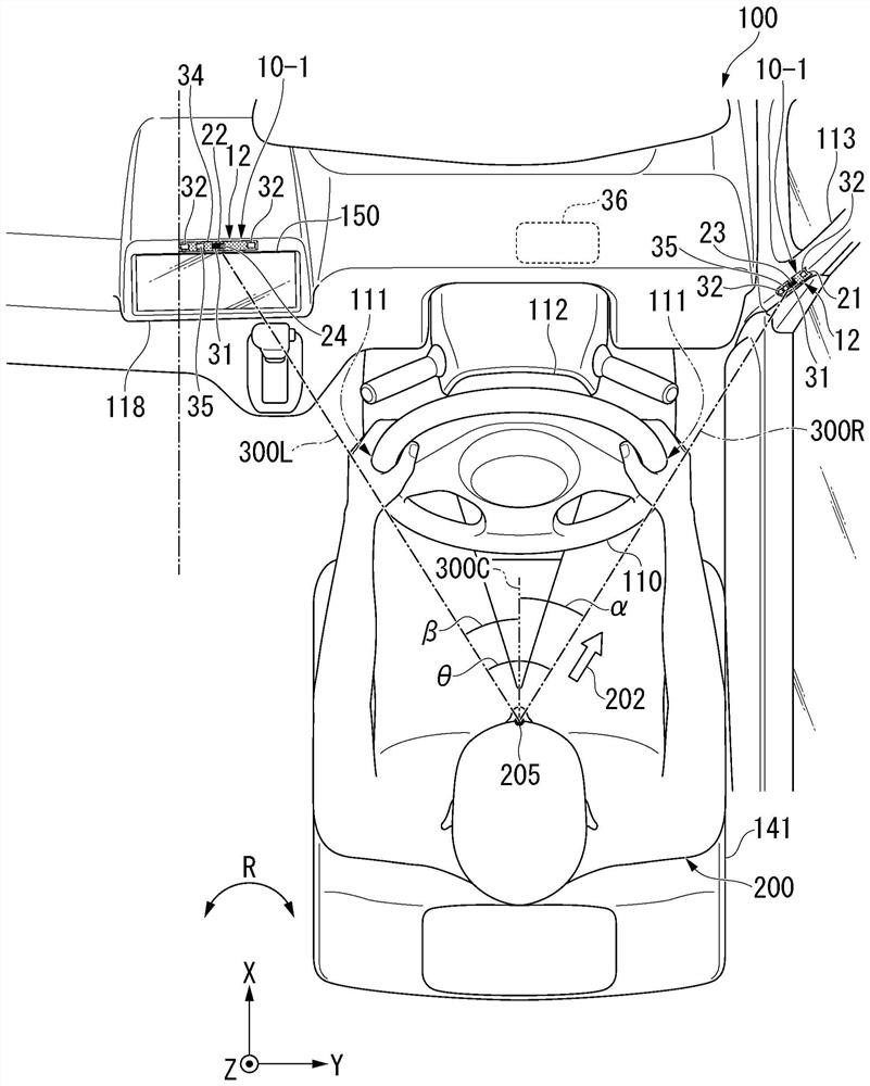
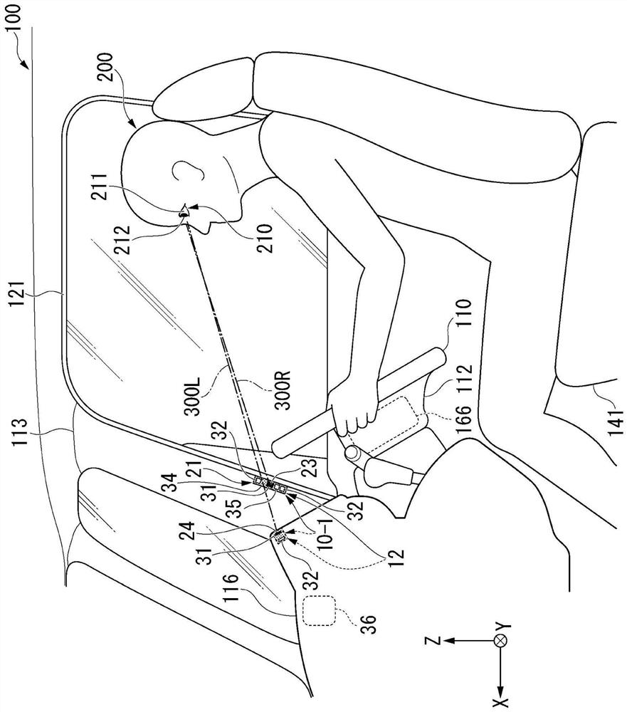
[0048] like figure 1 As shown, a driver's line of sight detection device (driver state detection device) 10 - 1 according to the first embodiment of the present invention is mounted on a vehicle 100 . The driver's line of sight detection device 10 - 1 includes a plurality of line of sight detection units 12 and an estimation unit 36 ​​. The driver's gaze detection device 10 - 1 is a device for estimating the gaze direction 202 of a driver 200 of the vehicle 100 .

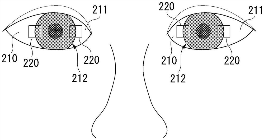
[0049] The gaze direction 202 is a direction in which the black eyeballs 212 of the driver 200 are directed regardless of the head orientation and rotation angle in a plan view centered on the viewpoint position 205 of the driver 200 . For example, even if the head of the driver 200 faces the front-rear direction X of the vehicle body when viewed from above with the viewpoint position 205 as the center, as long as the driver 200 passes through the black eyeball 212 (see figure 2 ) from the driver 200 and looking ...

no. 2 approach

[0092] Next, a driver's line of sight detection device (driver state detection device) 10-2 according to a second embodiment of the present invention will be described. Hereinafter, the description of the configuration of the driver's gaze detection device 10-2 shared with the driver's gaze detection device 10-1 will be omitted, and the configuration of the driver's gaze detection device 10-2 different from the driver's gaze detection device 10-1 will be described. exist Figure 5 and Figure 6 In the figure, the same reference numerals as those of the corresponding driver's line of sight detection device 10-1 are assigned to the components of the driver's line of sight detection device 10-2 shared with the driver's line of sight detection device 10-1.

[0093] like Figure 5 and Figure 6 As shown, in the driver's line of sight detection device 10-2, the second line of sight detection unit 22 is provided around the display unit 150 when viewed from the front and rear direc...


PUM


Abstract

The present invention provides a driver state detection device capable of detecting the line-of-sight direction of a driver with wide angle and high accuracy. The driver state detection device includes at least two state detection units (12) that include a first state detection unit (21) and a second state detection unit (22) that detect a state of a driver (200) of a vehicle (100), in which the first state detection unit (21) and the second state detection unit (22) are disposed at positions between which the driver (200) is interposed in a vehicle width direction (Y), and the first state detection unit (21) and the second state detection unit (22) are disposed in front of a rear end of a driver's seat.

Description

technical field [0001] The invention relates to a driver state detection device. Background technique [0002] In recent years, for the introduction of advanced safety support systems and automatic driving systems that accompany acceleration, braking, and steering control of vehicles, devices for detecting and confirming the driver's line of sight are installed in front of the driver in the vehicle (For example, refer to International Publication No. 2014 / 188648). [0003] However, in the conventional driver state detection device, when the driver's line of sight is directed toward a wide-angle direction that forms a relatively large angle from the driver's point of view in a plan view, the detection accuracy of the line of sight may decrease. For example, in the conventional driver state detection device, it may not be possible to detect with high accuracy that the driver's line of sight is directed toward the side mirror. Contents of the invention [0004] The aspect o...

Claims


Application Information

Patent Timeline
IPC IPC(8): B60W40/08B60W40/09
CPCB60W40/08B60W40/09B60W2540/223B60W2540/229B60K37/06B60K2370/149B60K2370/21G06V40/19G06V20/597B60K2370/176B60W2540/225B60W2420/403B60K2370/152B60K35/00
Inventor 丸山雅纪樋口实村上真一桥本敏宏
Owner HONDA MOTOR CO LTD
Why Eureka
Try Eureka