
A cable releaser

A pay-off and cable technology, applied in the field of cable processing, can solve problems such as stuck, unable to pull out the cable, and no rollback

Active Publication Date: 2022-05-20
深圳市鹏翔运达机械科技有限公司
View PDF11 Cites 1 Cited by
  • Summary
  • Abstract
  • Description
  • Claims
  • Application Information

AI Technical Summary

Problems solved by technology

This outer cover wire release structure causes the cables on the inner reel to be in a loose state all the time, and the cable layer above the reel will fall to cover the lower cable layer, and finally the cable layers will be superimposed, and the entire cable cannot be pulled out ,Stuck
[0006] 3. No retraction function: the machine retracts some cables after pulling too many wires, and the cables in the inner cover cannot be retracted to the reel at this time
The cable just falls loose on the ground, which is extremely irregular

Method used


Image

  • A cable releaser
  • A cable releaser
  • A cable releaser

Examples


Embodiment Construction

[0038] The present invention will be further described below in conjunction with specific embodiments.

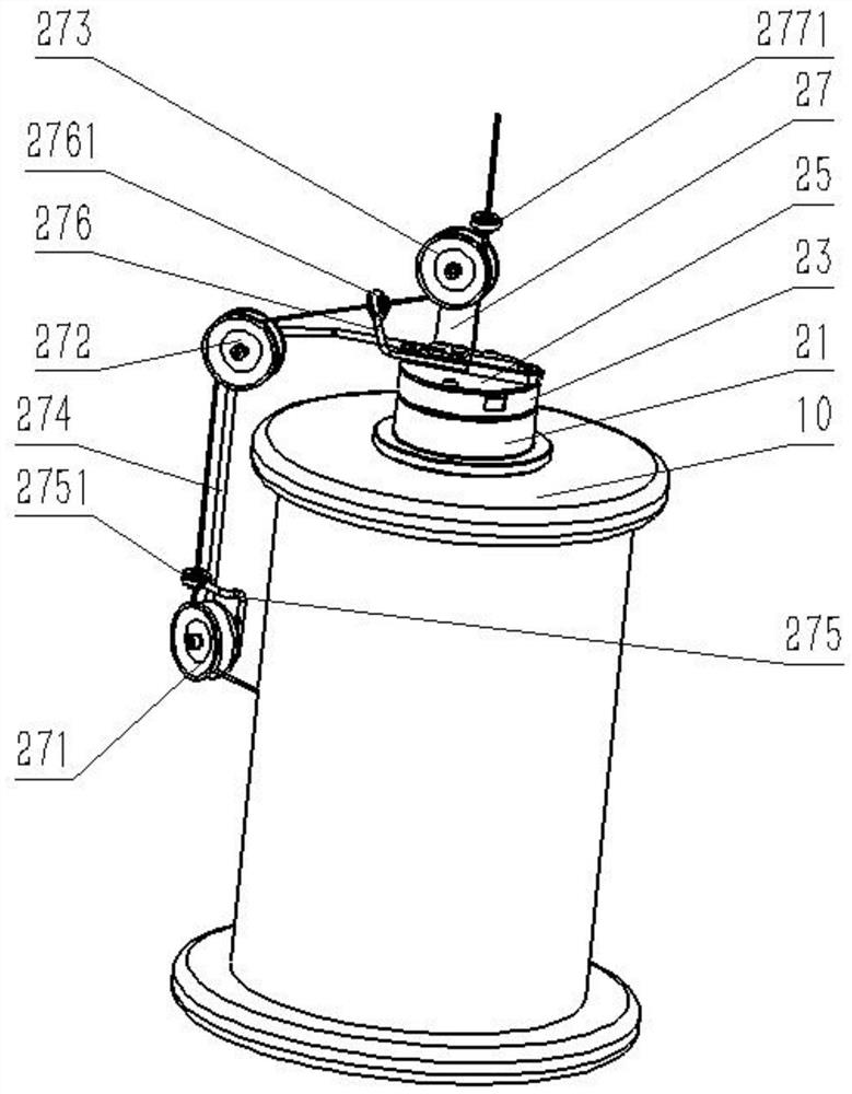
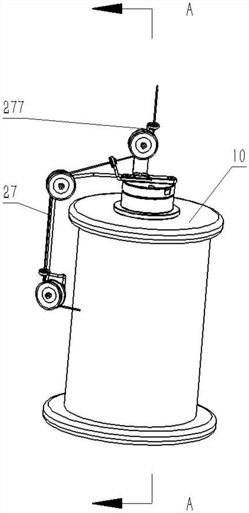
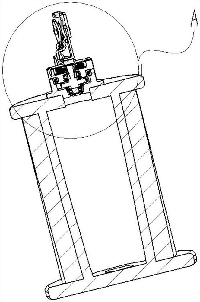
[0039] combine Figure 1-6, the present invention provides a cable pay-off device, the cable is wound on the industry standard reel 10, the center of the reel 10 is provided with a reel installation hole, including a pay-off that can be clamped and connected to the reel installation hole at the lower end The main body 21 of the pay-off device, the main body 21 of the pay-off device is an annular structure, the main body of the pay-off device 21 includes the first bearing position 211 and the second bearing position 212 arranged up and down; the central ratchet shaft 22 installed in the center of the main body 21 of the pay-off device, the central The lower end of the wheel shaft 22 is connected with the first bearing position 211 of the main body of the pay-off device through a bearing, and the central ratchet shaft 22 is provided with a ratchet 221 along the axial directio...


PUM


Abstract

The invention discloses a cable pay-off device, which includes a main body of the pay-off device whose lower end can be clamped and connected to the installation hole of a wire reel, and a central ratchet shaft connected to the main body of the wire release device through a bearing. The central ratchet shaft is arranged axially. There is a ratchet, the pawl elastically touches the ratchet and gives the ratchet a certain spring pressure. When the ratchet rotates, the spring pressure becomes the resistance to the ratchet rotation, and the ratchet gives the ratchet certain resistance to keep the cable in tension; through the bearing and the central ratchet shaft The rotating body connected to the upper end, the rotating body top cover fixed on the upper end of the rotating body and the lead frame fixed on the rotating body top cover, the knob-type elastic in the rotating body installation groove between the rotating body top cover and the rotating body One end of the knob-type elastic member is connected to the central ratchet shaft, and the other end of the knob-type elastic member is connected to the rotating body. The cable pay-off can achieve no friction, no damage to the cable, light tension at all times, the function of returning the cable to the reel, and no overlapping of cables.

Description

technical field [0001] The invention relates to the technical field of cable processing, in particular to a cable pay-off device. Background technique [0002] At present, the existing PT reel (ABS engineering plastic reel) is covered with thin copper wires, and is covered with a transparent shell cover when the wire is unwound. There is a porcelain eye installed on the top of the cover, and the cable is pulled out from the porcelain eye. The cable is also pulled out round and round on the reel. [0003] But there are big problems with this structure: [0004] 1. Scratch the cable: The way the outer cover is laid out is easy to scratch the cable. Although the upper and lower end faces of the PT reel have been rounded, the cable is still rubbing on the outer circle of the entire end face. , Bare copper wire or tinned wire, enameled wire will have friction loss, so this method will damage the cable for a long time. [0005] 2. No tensile stress, loose during unwinding: Duri...

Claims


Application Information

Patent Timeline
Patent Type & Authority Patents(China)
IPC IPC(8): B65H49/20B65H59/10B65H57/14
CPCB65H49/20B65H59/10B65H57/14
Inventor 陈磐彭杰
Owner 深圳市鹏翔运达机械科技有限公司
Learn More