Grouting device and grouting system

A technology of adjusting blocks and elastic parts, applied in construction, building maintenance, building construction, etc., can solve the problems of easy grout leakage, low artificial grouting efficiency, high grouting efficiency, etc., to reduce labor intensity, save manpower, and improve grouting efficiency Effect

Active Publication Date: 2020-12-08
GUANGDONG BOZHILIN ROBOT CO LTD
View PDF5 Cites 1 Cited by
  • Summary
  • Abstract
  • Description
  • Claims
  • Application Information

AI Technical Summary

Problems solved by technology

For this reason, the present invention proposes a grouting device, which can replace manual grouting to realize automatic grouting, has high grouting efficiency and is not easy to leak grout, and solves the technical problems of low manual grouting efficiency and easy grout leakage in the prior art

Method used


Image

  • Grouting device and grouting system
  • Grouting device and grouting system
  • Grouting device and grouting system

Examples


Embodiment 1

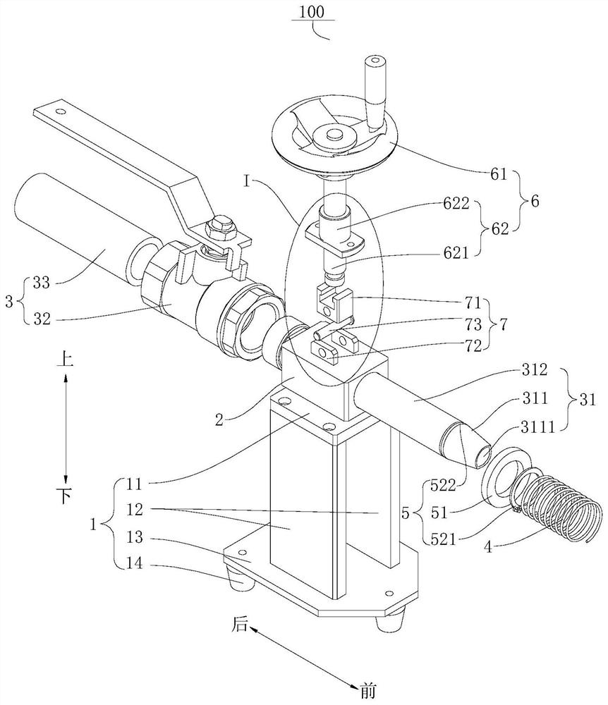
[0110] A grouting device 100, such as figure 1 As shown, it includes a bracket 1 , an adjustment block 2 , a grouting component 3 and an elastic member 4 .

[0111] Wherein, the adjusting block 2 is arranged on the support 1 in a liftable manner.

[0112] like figure 1 As shown, the grouting assembly 3 includes a grouting head 31, the grouting head 31 is slidably connected to the adjustment block 2, the side of the grouting head 31 away from the adjustment block 2 is provided with a limiting part 5, and the limiting part 5 has The locking position on the grouting head 31.

[0113] The elastic piece 4 is arranged between the limiting part 5 and the adjusting block 2, and when the elastic piece 4 drives the limiting part 5 to the locking position, the elastic piece 4 drives the grouting head 31 to move towards the grouting direction.

Embodiment 2

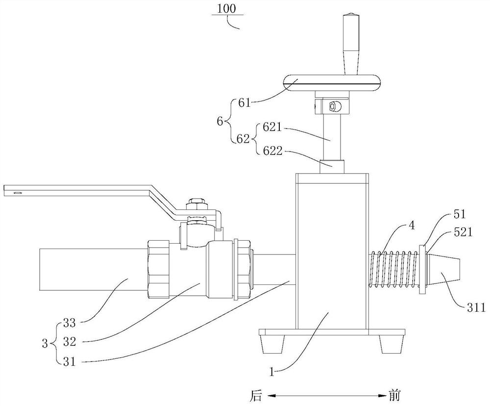
[0115] A grouting device 100, different from Embodiment 1, on the basis of Embodiment 1, such as Figure 5As shown, the limiting portion 5 includes a limiting ring 51 , and a stopping portion 52 is provided at the locking position. When the stretching length of the elastic member 4 is at a maximum, the limiting ring 51 is limited at the stopping portion 52 . The elastic member 4 is a spring, one end of the spring is connected with the limit ring 51 to move the support 1 when the elastic member 4 shrinks, and the other end of the spring is in contact with the adjustment block 2 .

Embodiment 3

[0117] A grouting device 100, different from Embodiment 2, on the basis of Embodiment 2, such as figure 1 As shown, the grouting head 31 includes a tapered portion 311 and an equal-diameter portion 312. One end of the equal-diameter portion 312 is connected to the tapered portion 311, and the end of the tapered portion 311 away from the equal-diameter portion 312 forms a grouting port 3111. A stop portion 52 is formed at the junction with the equal-diameter portion 312 , and the stop portion 52 protrudes from the surface of the grout head.

[0118] like Figure 5 As shown, the stop portion 52 includes a stop groove 522 and a clip 521, the clip 521 is detachably connected in the stop portion 52, one end surface of the stop ring 51 is abutted against the clip 521, and the stop ring 51 The other end surface is connected with the elastic member 4 .


PUM


Abstract

The invention discloses a grouting device and a grouting system. The grouting device comprises a support, an adjusting block, a grouting assembly and an elastic piece, wherein the adjusting block is arranged on the support in a liftable mode; the grouting assembly comprises a grouting head, wherein the grouting head is connected to the adjusting block in a front-back sliding mode, a limiting partis arranged on the side, away from the adjusting block, of the grouting head, the limiting part is provided with a clamped-stop position capable of being clamped and stopped on the grouting head, andthe elastic piece is arranged between the limiting part and the adjusting block; and when the elastic piece drives the limiting part to the clamped-stop position, the elastic piece drives the groutinghead to move towards the grouting direction. According to the grouting device, the adjusting block can drive the grouting head to move up and down to perform grouting on grouting holes with differentheights, and thus the application range of the grouting device is widened; and the elastic piece drives the grouting head to move towards the grouting direction, it is guaranteed that in the groutingprocess of the grouting head, part of the grouting head always extends into the grouting hole and is not prone to be detached from the grouting hole, and thus the grouting quality is improved.

Description

technical field [0001] The invention belongs to the technical field of building construction, in particular to a grouting device and a grouting system. Background technique [0002] Grouting refers to pressing the fluid and gelling grout into the cracks of the strata or buildings according to a certain ratio through drilling (or pre-buried pipes). Grouting can improve the impermeability and integrity of the filled ground or buildings, improve the foundation conditions, and improve the overall structure of the building. [0003] In the current building construction industry, the grouting work of buildings is mainly manual operation. During the grouting process, a single discharge pipe can be used as the grouting head. When grouting, the operator needs to hold the discharge pipe to align the grouting Hole construction, high work intensity and slow work efficiency, is not conducive to ensuring the scheduled construction progress. Moreover, the grouting hole of the building is...

Claims


Application Information

Patent Timeline
IPC IPC(8): E04G23/02
CPCE04G23/0203
Inventor 宋银灏苏俊超刘阳温光宇穆伟
Owner GUANGDONG BOZHILIN ROBOT CO LTD
Why Eureka
Try Eureka