Large-span truss supporting structure and construction method thereof
A technology for supporting structures and large spans, which is applied to pillars, building structures, and on-site preparation of building components, can solve problems such as troublesome truss support structures, save costs, reduce deformation, and facilitate construction.
- Summary
- Abstract
- Description
- Claims
- Application Information
AI Technical Summary
Problems solved by technology
Method used
Image
Examples
Embodiment 1
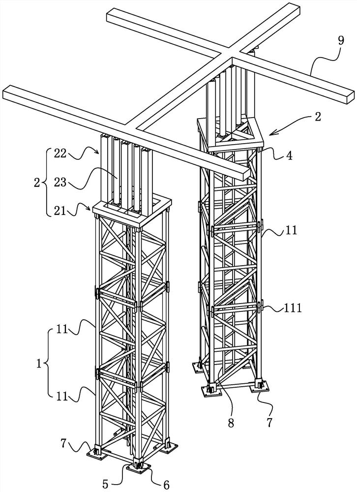
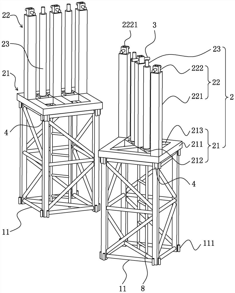
[0046] refer to figure 1 , the support structure for the large-span truss includes a tire frame 1 and an adjustment device 2, the tire frame 1 is fixed on the backing plate 7, the adjustment device 2 is positioned and installed on the top of the tire frame 1, the adjustment device 2 has an adjustable height, and the adjustment device 2 Where it conflicts with the lower chord 9 of the truss, the tire frame 1 and the adjustment device 2 provide stable support for the lower chord 9 of the truss.
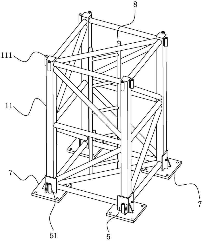
[0047] refer to figure 1The tire frame 1 includes a plurality of standard sections 11, and the tire frame 1 is formed by stacking the standard sections 11 up and down. The specification of the standard sections 11 is 1.8m*1.8m*2.8m, and the corners of the standard sections 11 are welded with threaded sleeves 111 , the bolt is inserted into the threaded sleeve 111 and threadedly matched with the threaded sleeve 111 to realize the fixation between the standard sections 11 . The inside o...
Embodiment 2
[0060] A construction method for a support structure of a long-span truss, comprising the following steps,
[0061] S1: Install the backing plate 7. By pouring concrete on the ground, the backing plate 7 is horizontally fixed on the concrete ground, and the supporting structure is placed on the backing plate 7 without causing damage to the backing plate 7.
[0062] S2: Fix the first standard section 11, clamp the threaded sleeve 111 on the standard section 11 through the clamping plate 5, and weld the clamping plate 5 on the backing plate 7, so that the first standard section 11 is stably fixed on the backing plate 7.
[0063] S3: stack the standard sections 11 up and down, and realize the fixing between the standard sections 11 by bolts, and finally form the tire frame 1 .
[0064] S4: Install the adjustment device 2 on the tire frame 1, and set the positioning plate 4 on the adjustment device 2 with the tire frame 1, and then the adjustment device 2 and the tire frame 1 mai...
PUM
 Abstract
Description
Claims
Application Information
 - R&D
- Intellectual Property
- Life Sciences
- Materials
- Tech Scout
- Unparalleled Data Quality
- Higher Quality Content
- 60% Fewer Hallucinations
Browse by: Latest US Patents, China's latest patents, Technical Efficacy Thesaurus, Application Domain, Technology Topic, Popular Technical Reports.
© 2025 PatSnap. All rights reserved.Legal|Privacy policy|Modern Slavery Act Transparency Statement|Sitemap|About US| Contact US: help@patsnap.com


