

Powdery ammonium phosphate drying device
A technology of drying device and ammonium phosphate, which is applied in the direction of drying gas arrangement, drying solid material, drying cargo handling, etc., can solve the problem of high cost of drying device, and achieve the effect of powerful drying function, high-efficiency drying and low cost
- Summary
- Abstract
- Description
- Claims
- Application Information
AI Technical Summary
Problems solved by technology
Method used
Image

Examples
Embodiment Construction
[0013] In order to make the object, technical solution and advantages of the present invention clearer, the present invention will be further described in detail below in conjunction with the accompanying drawings and embodiments. It should be understood that the specific embodiments described here are only used to explain the present invention, not to limit the present invention.
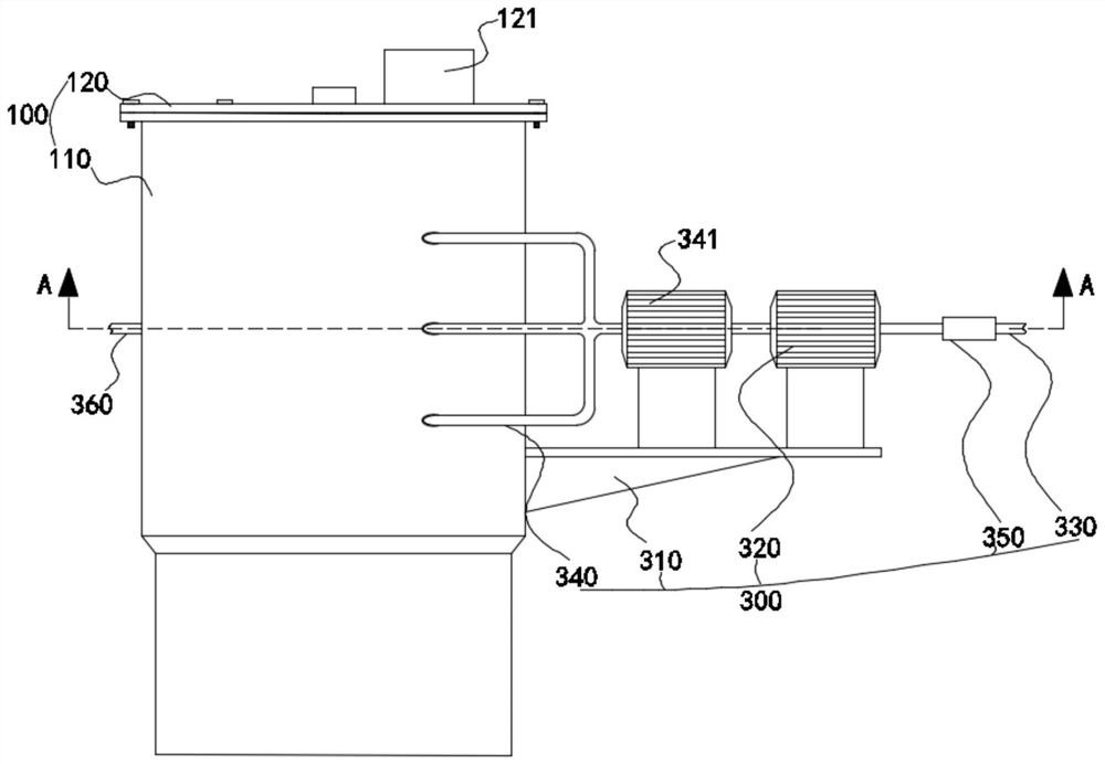
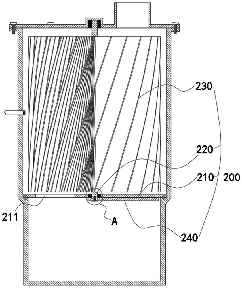
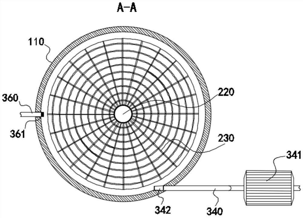
[0014] Such as Figure 1-2 As shown, the present invention provides a kind of powdery ammonium phosphate drying device, comprises drying box 100, stirring assembly 200 and air supply assembly 300, during implementation, air supply assembly 300 sends hot blast in drying box 100, and hot blast blows to stirring assembly 200, to drive the stirring assembly 200 to rotate. During the process of drying the powdery ammonium phosphate in the drying box 100 by the hot air, the stirring assembly 200 rotates to achieve stirring treatment on the powdery ammonium phosphate, so that the drying effect can be bett...
PUM
 Abstract
Description
Claims
Application Information