Textile cloth printing, dyeing and drying device

A technology of drying device and textile cloth, applied in drying, dryer, drying gas arrangement and other directions, can solve problems such as affecting product quality, affecting the internal environment of the box, easy fading of pigments, etc., to promote thorough drying, The effect of speeding up drying efficiency and promoting the removal of moisture from the fabric

Active Publication Date: 2020-12-08
泉州台商投资区飞翔机械设计服务中心
View PDF17 Cites 2 Cited by
  • Summary
  • Abstract
  • Description
  • Claims
  • Application Information

AI Technical Summary

Problems solved by technology

The most important thing after the dyeing is to dry the dyed cloth. This step determines the coloring of the dyed cloth. If the drying is not complete, the pigment on the dyed cloth will fade easily, which will greatly affect the product. The quality of the cloth; and when the cloth is dried, water vapor will be generated. If it is not treated in time, it will adversely affect the drying efficiency of the cloth and affect the environment inside the box.

Method used


Image

  • Textile cloth printing, dyeing and drying device
  • Textile cloth printing, dyeing and drying device

Examples


Embodiment

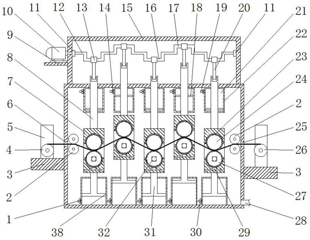
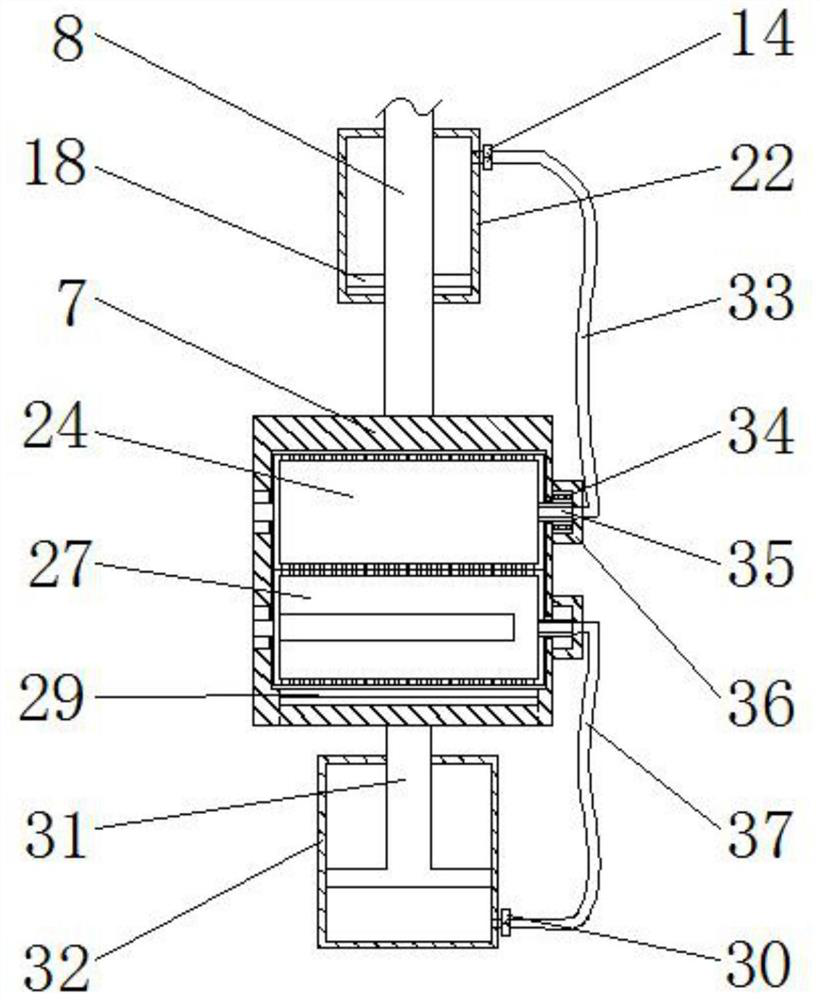
[0024] Such as figure 1A textile printing and dyeing drying device shown includes a box with an electric heating element (not shown in the figure) inside, and two opposite sides of the box are respectively provided with a cloth inlet 6 and a cloth outlet 25 aligned with each other. , the opposite sides of the cloth inlet 6 and the cloth outlet 25 are respectively provided with a set of conveying rollers 2 for conveying the cloth in the box, and at least two lifting frames 7 are arranged at equal intervals between the two sets of conveying rollers 2 ( Five lifting frames 7 are shown in the accompanying drawings), and the blowing cylinder 24 and the suction cylinder 27 for clamping cloth are provided in the lifting frame 7, and the blowing cylinder 24 and the suction cylinder 27 are both Parallel to the conveying roller group 2, and the suction cylinder 27 is located below the blowing cylinder 24, the end faces of the blowing cylinder 24 and the suction cylinder 27 are all close...


PUM


Abstract

The invention discloses a textile fabric printing, dyeing and drying device, and belongs to the field of drying equipment. The textile fabric printing, dyeing and drying device comprises a box body internally provided with an electric heating element, two or more lifting frame bodies are arranged in the box body at equal intervals, the tops of the lifting frame bodies are connected with lifting rods, and the upper ends of the lifting rods are connected with a lifting driving mechanism; an air blowing roller and an air suction roller which are used for clamping a cloth are arranged in each lifting frame body, and through holes are evenly spread over the side faces of the air blowing rollers and the air suction rollers; and the air blowing rollers communicate with a first air cylinder arranged at the top in the box body through a first exhaust pipe, the air suction rollers communicate with a second air cylinder arranged at the bottom in the box body through a second air inlet pipe, condensers are arranged in the air suction rollers, the lower ends of the lifting frame bodies are provided with liquid discharging channels communicating with the two sides of the lifting frame bodies, and the bottom of one side of the box body is connected with a liquid discharging pipe. The textile fabric printing, dyeing and drying device is high in drying efficiency, can be thoroughly dry the cloth, can treat water vapor generated in the drying process in time and thus can avoid the adverse effects on the drying efficiency of the cloth, and the environment in the box body is maintained advantageously.

Description

technical field [0001] The invention relates to the field of drying equipment, in particular to a textile fabric printing and dyeing drying device. Background technique [0002] The development prospect of the textile industry is very huge. The textile industry will always accompany our life and is closely related to our life. The clothes we wear all need textiles to complete. With the improvement of our country's economic level, the color of our clothes is no longer black, white and gray. All kinds of colors accompany our clothes to reflect our colorful and diverse personalities. The appearance of these clothes in various colors is attributed to the improvement of dyeing technology, which is an important step in the development of textiles, and the improvement of dyeing technology drives the development of the textile industry. The most important thing after the dyeing is to dry the dyed cloth. This step determines the coloring of the dyed cloth. If the drying is not compl...

Claims


Application Information

Patent Timeline
Patent Type & Authority Applications(China)
IPC IPC(8): F26B13/08F26B21/00F26B25/00F26B25/02F26B25/20B65H18/10
CPCB65H18/103F26B13/08F26B21/001F26B21/004F26B25/00F26B25/02F26B25/20
Inventor 林飞燕
Owner 泉州台商投资区飞翔机械设计服务中心
Why Eureka
Try Eureka