Indoor positioning and navigation method and system based on computer vision

A computer vision and indoor positioning technology, applied in the field of indoor navigation, can solve problems such as inability to accurately distinguish between different floors, satellite signal blocking, and inability to achieve positioning

Active Publication Date: 2020-12-08
NORTH CHINA ELECTRIC POWER UNIV (BAODING)
View PDF9 Cites 11 Cited by
  • Summary
  • Abstract
  • Description
  • Claims
  • Application Information

AI Technical Summary

Problems solved by technology

But indoors, satellite signals are easily blocked by buildings, making positioning impossible
At the same time, GNSS technology can only distinguish the plane position, is not sensitive to height information, and cannot accurately distinguish different floors
Although mobile phone wireless communication signals can penetrate the walls of most buildings, the distribution density of mobile communication base stations is too low, and the positioning accuracy of the "nearest neighbor method" can reach several kilometers. Accuracy is also 200m

Method used


Image

  • Indoor positioning and navigation method and system based on computer vision
  • Indoor positioning and navigation method and system based on computer vision
  • Indoor positioning and navigation method and system based on computer vision

Examples


Embodiment 1

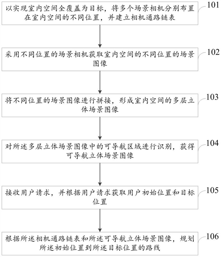
[0089] The present invention takes the navigation object as a car, and describes the navigation method when the navigation object of the present invention is a robot. Specifically include the following steps:

[0090] Step 1: First install the camera in the indoor area where navigation is required, and the camera should be installed as high as possible. The installation of the camera can be mixed with the dome camera and the bolt camera to ensure that the field of view of all cameras can cover the navigation area, and there is a certain overlapping coverage area between two cameras. When an area is full of guns, directional positioning and navigation is used; when an area is mixed with guns and ball machines, omnidirectional positioning and navigation is used. All cameras are numbered.

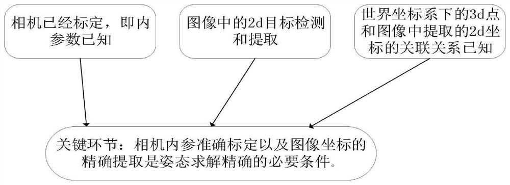
[0091] Step 2: After installing all cameras, use Zhang Zhengyou calibration method to calibrate the cameras. Obtain the internal and external parameters of the camera, and correct the image...

Embodiment 2

[0128] Embodiment 2: Orientation positioning navigation

[0129] Orientation and positioning navigation, its mode is mainly to install the camera with a fixed angle of view such as Image 6 , the viewing angles of different cameras are intersected or there are connection points where the two viewing angles do not intersect, such as Figure 7 The interior of the room: from the perspective of the corridor and the perspective of the door, the door is a connection point. V1-V9 indicates the number of the camera, the field of view of the camera can cover the area that may be navigated indoors, and D1-D9 indicates the connection point between the cameras. In this mode, builds such as Figure 8 The linked list of cameras. All cameras are fixed, by retrieving the navigation object in all camera views, and then positioning.

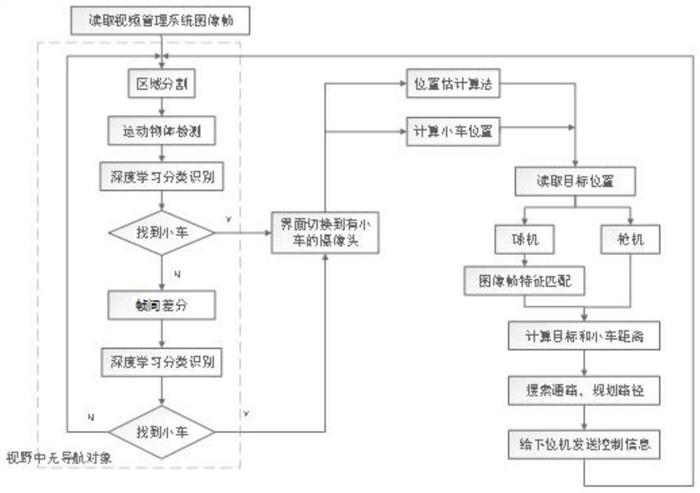
[0130] like Figure 5 It is a flow chart of the navigation method based on orientation and positioning provided by the embodiment of the present application....

Embodiment 3

[0142] Embodiment 3: Omni-directional positioning and navigation

[0143] The difference between omnidirectional positioning navigation and directional positioning navigation is that: the angle of view of the omnidirectional positioning navigation camera is not fixed, but can be controlled to rotate; the angle of view of the directional positioning navigation camera cannot be rotated. Omni-directional positioning and directional positioning can complement each other. Under omni-directional positioning navigation, when the camera detects the navigation object, it will adjust the camera's field of view, that is, it will rotate with the movement of the navigation object, so that the navigation object is always in the best position in the field of view. For example in Figure 4 In the corridor, install a dome camera at the center of the corridor, the schematic diagram is as follows Figure 14 ;When the car appears at the end of the corridor, through the detection of the navigati...


PUM


Abstract

The invention provides an indoor positioning and navigation method and system based on computer vision. The method comprises the following steps: firstly, aiming at realizing full coverage of an indoor space, respectively arranging a plurality of scene cameras at different positions of the indoor space, and establishing a camera access linked list; adopting scene cameras at different positions toobtain scene images at different positions of the indoor space; splicing the scene images at different positions and identifying a navigable area to obtain a navigable two-dimensional scene image; then, receiving a user request, and obtaining an initial position and a target position of a user according to the user request; and planning a route from the initial position to the target position according to a camera access linked list and the navigable two-dimensional scene image. According to the invention, a navigable two-dimensional scene image and a camera access linked list for indoor navigation are established based on a scene image acquired by a scene camera, route planning is carried out on a user request, and navigation is carried out on a person or a robot according to a planned route.

Description

technical field [0001] The invention relates to the technical field of indoor navigation, in particular to a method and system for indoor positioning and navigation based on computer vision. Background technique [0002] The space for human activities is becoming larger and more complex and most of the time they stay indoors. The positioning and guiding needs of parking lots, shopping malls, airports, office buildings and other places are becoming increasingly strong. At the same time, industries such as intelligent manufacturing and indoor service robots also urgently need computers to be able to identify the location of specific objects indoors. This demand brings great opportunities for indoor positioning technology. Despite the strong demand for indoor positioning, traditional positioning technologies (satellite positioning, base station positioning) cannot meet the needs of indoor positioning due to technical limitations. [0003] Satellite positioning technology (Gl...

Claims


Application Information

Patent Timeline
Patent Type & Authority Applications(China)
IPC IPC(8): G01C21/20G06T3/40G06T7/11G06T7/70
CPCG01C21/206G06T3/4038G06T7/11G06T7/70G06T2207/20081G06T2207/20084
Inventor 姚万业冯涛明杨明玉
Owner NORTH CHINA ELECTRIC POWER UNIV (BAODING)
Why Eureka
Try Eureka