
Computable reconfigurable machine tool geometric pose error defining method

An error and pose technology, applied in the field of computable and reconfigurable machine tool geometric pose error definition, which can solve problems such as inseparability of professional knowledge and difficulty in updating the production site.

Active Publication Date: 2020-12-08
YANGZHOU UNIV
View PDF13 Cites 4 Cited by
  • Summary
  • Abstract
  • Description
  • Claims
  • Application Information

AI Technical Summary

Problems solved by technology

[0005] The purpose of the present invention is to provide a computationally reconfigurable machine tool geometric pose error definition method to solve the existing geometric pose error definition method in the prior art is inseparable from professional knowledge, geometric pose error requires professional knowledge Personnel redefine according to different machine tool structures, technical problems that are difficult to update in time at the production site

Method used


Image

  • Computable reconfigurable machine tool geometric pose error defining method
  • Computable reconfigurable machine tool geometric pose error defining method
  • Computable reconfigurable machine tool geometric pose error defining method

Examples


Embodiment Construction

[0044] The present invention will be further described below in conjunction with specific embodiments. The following examples are only used to illustrate the technical solution of the present invention more clearly, but not to limit the protection scope of the present invention.

[0045] The invention provides a computationally reconfigurable geometric pose error definition method of a machine tool, comprising the following steps:

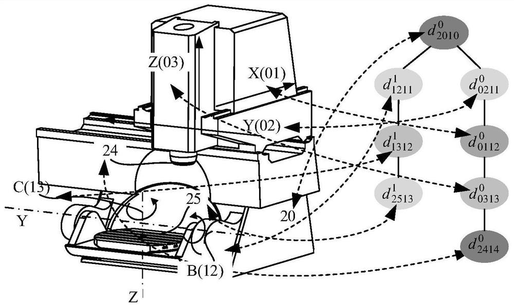
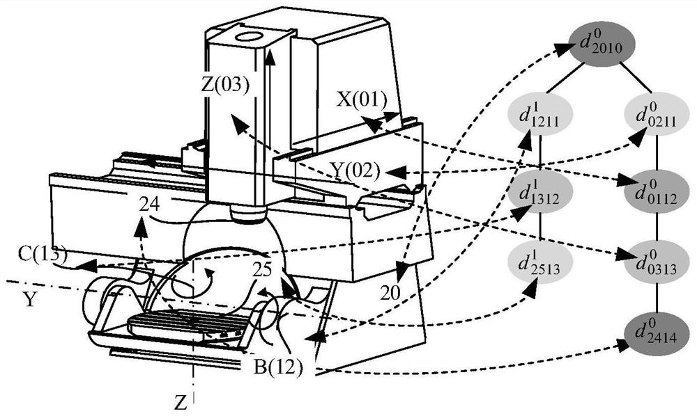
[0046] Step 1: Determine the description method of the reconfigurable machine tool node module, specifically described as:

[0047]

[0048] In formula (1), Refers to the node module elements in the node module set D; r is used to distinguish the position of the node module in the reconfigurable machine tool configuration tree model, if r=0, the node module is in the tool branch, if r=1, the node module is in Workpiece branch; a is used to distinguish different motion attributes. When a=0, the corresponding node module refers to the linear ax...


PUM


Abstract

The invention discloses a computable reconfigurable machine tool geometric pose error definition method. The method comprises the following steps: firstly, establishing a reconfigurable machine tool configuration tree model, and defining a geometric pose error general expression and a pose error definition coefficient matrix of a linear axis motion module and a rotating axis motion module; then determining a linear axis geometric pose error definition sequence and a mapped module type on the basis of the configuration tree model, designing a linear axis geometric pose error definition operator, and calculating a pose error definition coefficient matrix of the linear axis; designing a rotating shaft geometric pose error definition operator to determine a rotating shaft pose error definitioncoefficient matrix according to the rotating shaft type; and finally, realizing definition of the reconfigurable machine tool geometric pose error through adaptive calculation of the coefficient matrix. Intelligent definition of reconfigurable machine tool geometric pose errors can be achieved through a programming calculation method so as to adapt to continuously changing machine tool structureconfiguration, and experience requirements of operators are reduced.

Description

technical field [0001] The invention relates to the field of definition of machine tool geometric pose error, in particular to a method for defining the geometric pose error of a computable and reconfigurable machine tool. Background technique [0002] In recent years, with the transformation and upgrading of the manufacturing industry and the development of the service manufacturing industry, dynamically changing product manufacturing requirements and shorter product cycles have brought challenges to manufacturing companies. Manufacturing companies can update their manufacturing systems in real time to ensure market competitiveness. Modular reconfigurable machine tools are one of the effective solutions for manufacturing companies to respond to market changes. Reconfigurable machine tools are mass-produced and flexible manufacturing equipment that provide user-customized functions. They can economically and efficiently adjust configuration and production capacity according ...

Claims


Application Information

Patent Timeline
IPC IPC(8): G05B19/404B23Q17/22
CPCB23Q17/2233G05B19/404
Inventor 丁爽宋占群俞亮吴伟伟
Owner YANGZHOU UNIV
Learn More