Nonreciprocal circuit device

A circuit device, non-reciprocal technology, applied in the field of non-reciprocal circuit devices, can solve the problems of increasing device size, cost increase, device inability to meet miniaturization and cost reduction, etc.

Inactive Publication Date: 2003-09-03
MURATA MFG CO LTD
View PDF0 Cites 0 Cited by
  • Summary
  • Abstract
  • Description
  • Claims
  • Application Information

AI Technical Summary

Problems solved by technology

This leads to the problem of using an extra filter which leads to an increase in cost due to extra parts and increases the size of the device
That is, conventional devices cannot meet the requirements of miniaturization and cost reduction

Method used


Image

  • Nonreciprocal circuit device
  • Nonreciprocal circuit device
  • Nonreciprocal circuit device

Examples


Embodiment Construction

[0030] Referring to the accompanying drawings, preferred embodiments of the present invention will be described.

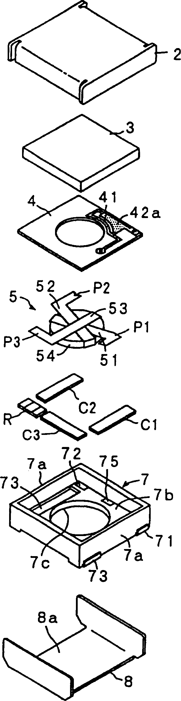
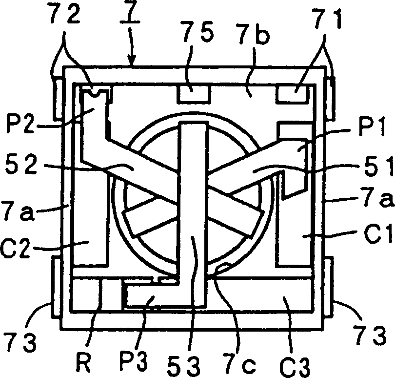
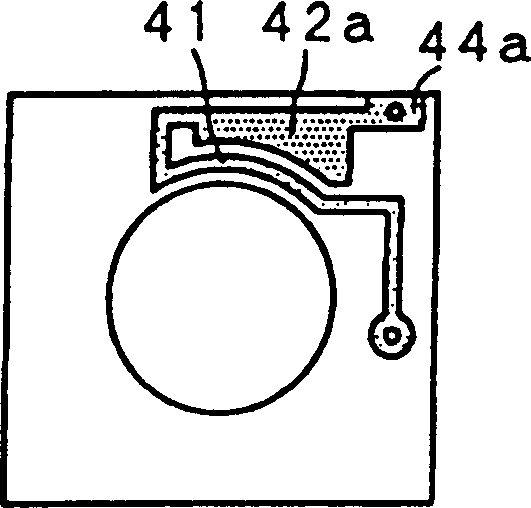
[0031] Figure 1 to Figure 4 The structure and arrangement of an embodiment of an isolator according to the invention is shown. figure 1 is an exploded perspective view of the isolator; figure 2 is the plan view of the isolator with the spacer, permanent magnet and upper yoke removed; Figure 3A is a plan view showing the front (upper side) of the gasket, and Figure 3B is a plan view showing the back (lower side) of the gasket; and Figure 4 is the equivalent circuit diagram.

[0032] Such as figure 1 As shown in 3, the isolator used in the embodiment has such an arrangement that a permanent magnet 3 is provided on the inner surface of a box-shaped upper yoke 2 made of a magnetic material; the yoke 2. A substantially U-shaped lower yoke 8 is loaded, and the lower yoke 8 is similarly made of a magnetic material so as to form a closed magnetic circuit; the...


PUM


Abstract

A nonreciprocal circuit device which can achieve miniaturization and cost reduction by increasing attenuation outside a passband and greatly decreasing the occurrence of extraneous radiation emissions. The nonreciprocal circuit device comprises a magnetic circuit, a magnetic assembly, a plurality of matching capacitors, a resin case, and a spacer; the filter inductor is connected between said port of one of the central conductors and an input / output terminal corresponding to the port; the filter capacitor is connected between said input / output terminal and said ground; whereby a low-pass filter is formed by the filter inductor, the filter capacitor, and the matching capacitor.

Description

technical field [0001] The present invention relates to non-reciprocal circuit devices such as isolators, circulators and the like for high frequency bands such as microwave bands. In particular, the present invention relates to such a non-reciprocal circuit device which can be miniaturized and reduced in cost when used in a mobile communication device. Background technique [0002] In general, a non-reciprocal device such as a lumped constant type isolator or a circulator is characterized by an extremely small amount of attenuation of a signal in the direction in which the signal is transmitted and a large amount of attenuation in the opposite direction. This traditional type of isolator includes features such as Figure 7 Devices of the structure shown in . A conventional isolator has a structure in which parts including a permanent magnet 3; a spacer 14; a magnetic assembly 5 including three central conductors 51, 52, and 53 and a ferrite element 54; and a resin case 7 a...

Claims


Application Information

Patent Timeline
Patent Type & Authority Patents(China)
IPC IPC(8): H01P1/383H01P1/36H01P1/387
CPCH01P1/387H01P1/215H01P1/36
Inventor 牧野敏弘川浪崇长谷川隆
Owner MURATA MFG CO LTD
Why Eureka
Try Eureka