A valve base control and protection method

A technology of valve base control and valve base control equipment, which is applied to emergency protection circuit devices, power transmission AC networks, electrical components, etc., can solve problems such as sub-module damage, sub-module IGBT avalanche breakdown, etc., to improve reliability, The effect of reducing voltage stress

Active Publication Date: 2022-08-05
STATE GRID CORP OF CHINA +1
View PDF0 Cites 0 Cited by
  • Summary
  • Abstract
  • Description
  • Claims
  • Application Information

AI Technical Summary

Problems solved by technology

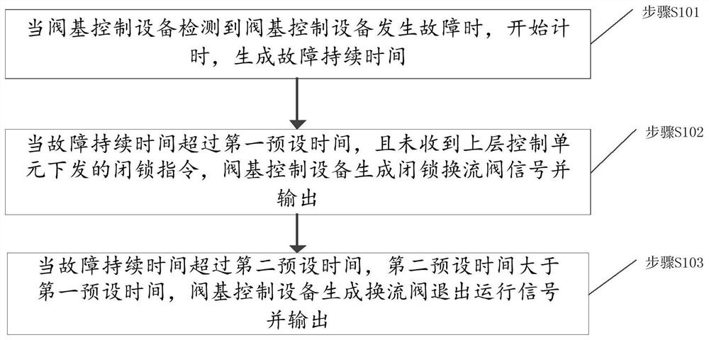
[0006] In view of this, the embodiment of the present invention provides a valve-base control and protection method to solve the problem in the prior art that when the valve-base control device fails, the sub-module is damaged, and in severe cases, it will cause avalanche breakdown of a large number of sub-module IGBTs

Method used


Image

  • A valve base control and protection method
  • A valve base control and protection method
  • A valve base control and protection method

Examples


Embodiment Construction

[0022] The technical solutions of the present invention will be clearly and completely described below with reference to the accompanying drawings. Obviously, the described embodiments are a part of the embodiments of the present invention, but not all of the embodiments. Based on the embodiments of the present invention, all other embodiments obtained by those of ordinary skill in the art without creative efforts shall fall within the protection scope of the present invention.

[0023] In the description of the present invention, it should be noted that the terms "center", "upper", "lower", "left", "right", "vertical", "horizontal", "inner", "outer", etc. The indicated orientation or positional relationship is based on the orientation or positional relationship shown in the accompanying drawings, which is only for the convenience of describing the present invention and simplifying the description, rather than indicating or implying that the indicated device or element must hav...


PUM


Abstract

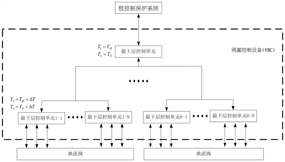
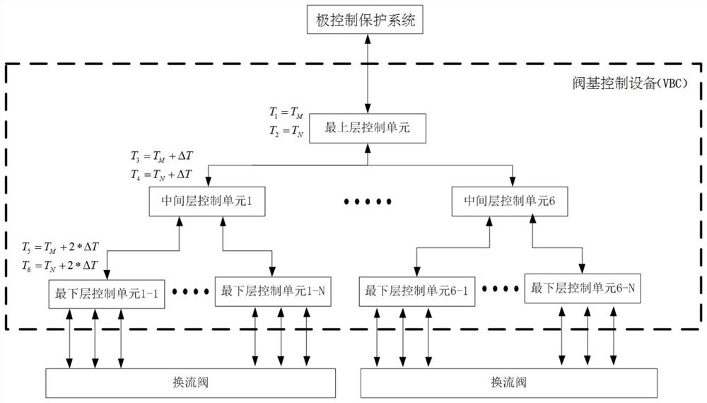
The invention discloses a valve base control and protection method, which includes: when a valve base control device detects a failure of the valve base control device, starts timing, and generates a fault duration; when the fault duration exceeds a first preset time and does not stop After receiving the blocking instruction issued by the upper-level control unit, the valve base control device generates and outputs the blocking converter valve signal; when the fault duration exceeds the second preset time, and the second preset time is greater than the first preset time, the valve base controls The device generates and outputs a signal that the converter valve is out of operation. By implementing the present invention, without additionally increasing the physical connection between each control unit, when any layer of the valve-based control equipment fails, the converter valve can be controlled to smoothly transition to the state of blocking and shutdown, ensuring the entire process The converter valves are all in a controlled state; and strategies such as redundant system switching and all sub-modules are blocked at the same time as much as possible to reduce the voltage pressure on the converter valve sub-modules in the event of a fault.

Description

technical field [0001] The invention relates to the technical field of flexible direct current transmission, in particular to a valve base control and protection method. Background technique [0002] Flexible DC transmission based on Modular Multilevel Converter (MMC) is known as the third generation of transmission technology after AC transmission and conventional DC transmission. Load power supply, grid interconnection, island / drilling platform power supply and other fields have broad application prospects. [0003] The core equipment of HVDC flexible transmission project mainly includes converter valve (VALVE), valve-based control equipment (ValveBased Control, VBC) and pole control and protection system (Pole Control and Protection, PCP). Among them, the converter valve is responsible for the DC-AC conversion and AC-DC conversion in the flexible DC transmission project. Hundreds or even thousands of sub-modules are connected in series, and each sub-module must be indivi...

Claims


Application Information

Patent Timeline
Patent Type & Authority Patents(China)
IPC IPC(8): H02H7/122H02H7/125H02J3/36
CPCH02H7/122H02H7/125H02J3/36Y02E60/60
Inventor 谢敏华路建良唐茹彬李强武思捷
Owner STATE GRID CORP OF CHINA
Why Eureka
Try Eureka