Welding treatment repairing system for architectural profile of steel structure
A repair system, construction steel technology, applied in the field of construction steel structure profile welding processing repair system, can solve the problems of deformation, failure to obtain construction steel structure, steel structure cannot be assembled, etc.
- Summary
- Abstract
- Description
- Claims
- Application Information
AI Technical Summary
Problems solved by technology
Method used
Image


Examples
Embodiment Construction
[0025] In order to make the technical means, creative features, goals and effects achieved by the present invention easy to understand, the present invention will be further described below in conjunction with specific illustrations.
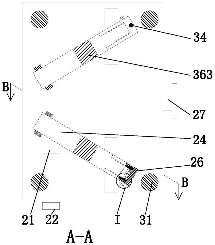
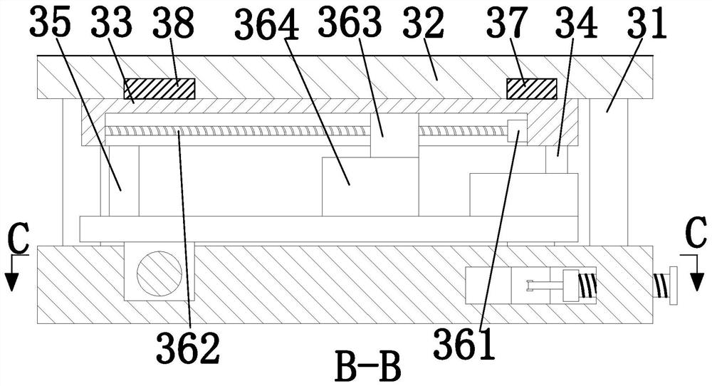
[0026] Such as Figure 1 to Figure 6 As shown in the figure, a welding treatment and repair system for building steel structure profiles includes a seat 1, an adjustment and fixing unit 2 and a positioning repair unit 3. The middle part of the upper end of the seat 1 is provided with an adjustment and fixing unit 2, and the upper end of the seat 1 is provided with a positioning repair unit. 3. Adjust the fixing mechanism 2 to fix the steel plates, and connect the two steel plates according to the angle, and the positioning repair unit 3 straightens the bent steel plates.
[0027] The adjustment and fixing unit 2 includes a threaded column 21, a rotating hand wheel 22, a feed block 23, a feed platform 24, a fixing mechanism 26 and an adjusting me...
PUM
 Abstract
Description
Claims
Application Information
PatSnap Eureka turns technology decisions into work you can execute. Powered by our Innovation Knowledge Graph, it runs expert workflows across engineering, life sciences, materials and intellectual property. Get your review-ready output in minutes.


