Shakeout machine for sand mold casting

A technology of sand casting and shakeout machine, applied in the field of sand casting, can solve the problems of no shock absorption mechanism, low efficiency, shortened service life of the device, etc., to save time, improve the efficiency of falling sand, and reduce vibration.

Inactive Publication Date: 2020-12-11
安翔
View PDF6 Cites 9 Cited by
  • Summary
  • Abstract
  • Description
  • Claims
  • Application Information

AI Technical Summary

Problems solved by technology

[0006] The purpose of the present invention is to solve the problem in the prior art that it can only vibrate up and down, the efficiency is low, and the service life of the device is reduced due to the absence of a shock absorbing mechanism, and a shakeout machine for sand casting is proposed.

Method used


Image

  • Shakeout machine for sand mold casting
  • Shakeout machine for sand mold casting
  • Shakeout machine for sand mold casting

Examples


Embodiment 1

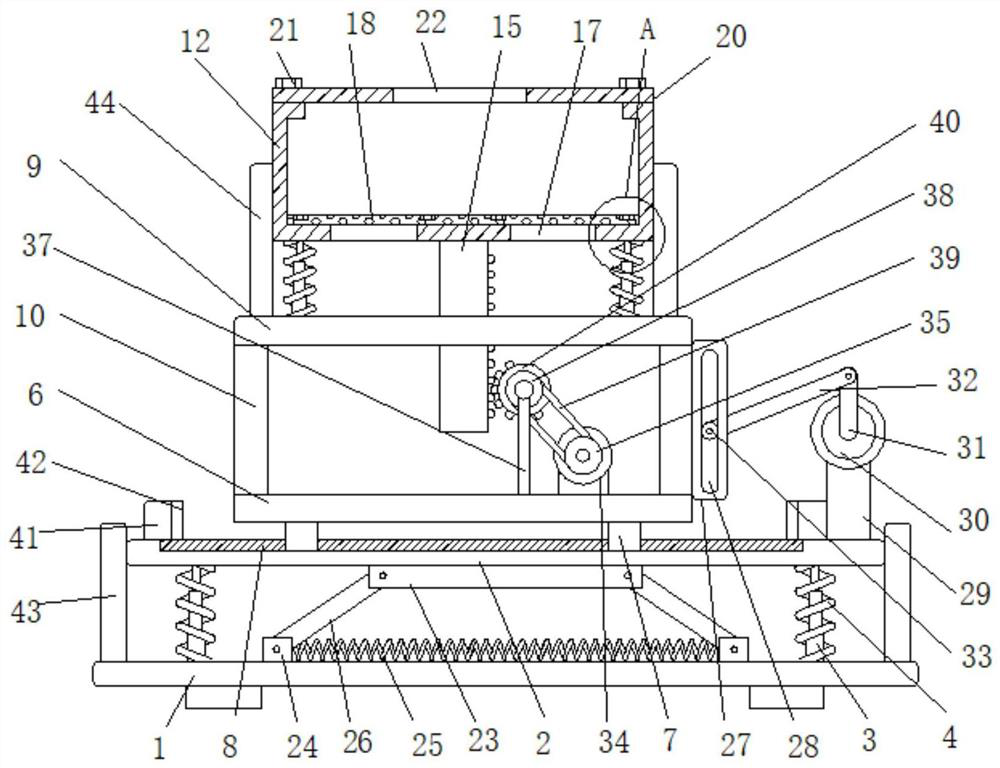
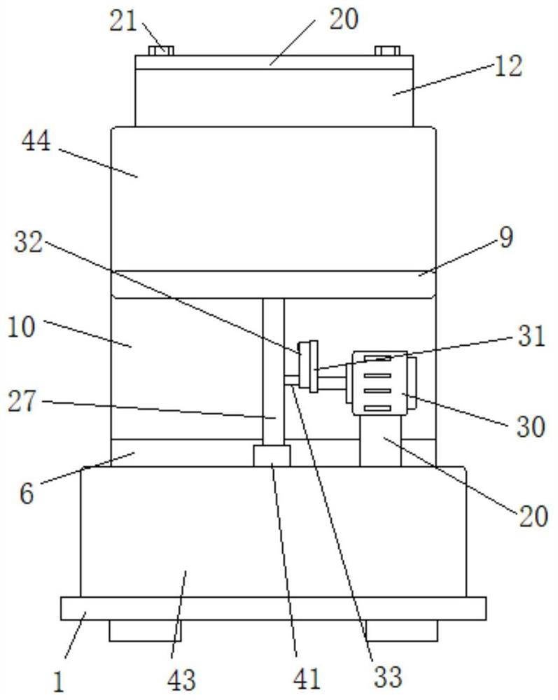
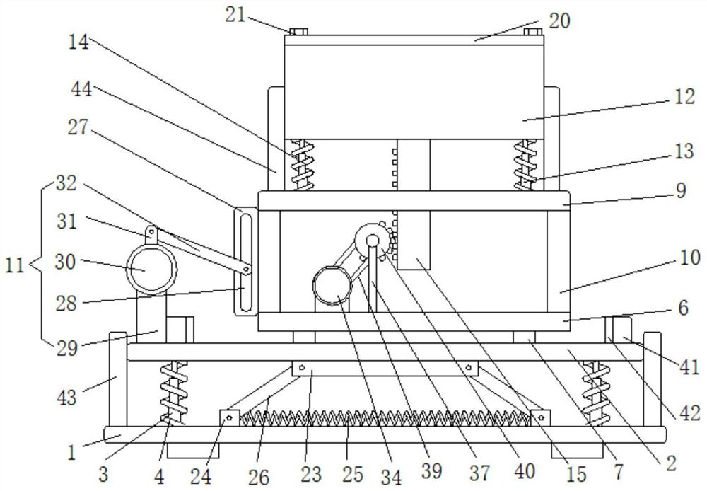
[0031] Embodiment one, such as Figure 1-7As shown, a shakeout machine for sand casting includes a first base plate 1 arranged horizontally, a second base plate 2 is arranged horizontally above the first base plate 1, and the second base plate 2 passes through a plurality of first telescopic rods 3 vertically arranged It is fixedly connected with the first base plate 1, and the second base plate 2 is fixedly connected with the first base plate 1 through a plurality of vertically arranged first springs 4, and the plurality of first springs 4 are respectively wound on the corresponding first telescopic rods 3. A damping mechanism 5 is provided between the first base plate 1 and the second base plate 2, and a first fixed plate 6 is horizontally arranged above the second base plate 2, and a plurality of sliders 7 are fixedly connected to the bottom surface of the first fixed plate 6, and the second base plate 2 The upper surface is provided with a chute 8, the chute 8 is slidably ...

Embodiment 2

[0032] Embodiment two, such as figure 1 , 3 , 6, the damping mechanism 5 includes a damping plate 23 fixedly connected to the bottom surface of the second base plate 2, the damping plate 23 is horizontally arranged, and the upper surface of the first base plate 1 is slidingly connected with two damping blocks 24, two damping blocks 24 The shock block 24 is fixedly connected by a plurality of third springs 25 arranged horizontally, and both ends of the shock absorbing plate 23 are rotatably connected with first connecting rods 26, and the ends of the two first connecting rods 26 far away from the shock absorbing plate 23 are connected to the same side respectively. The corresponding damping block 24 is rotationally connected, and the vertical force is decomposed into the driving force of the shock absorbing block 24 in the horizontal direction through the first connecting rod when the second bottom plate 2 vibrates up and down by setting the shock absorbing plate 23. Then the ...

Embodiment 3

[0033] Embodiment three, such as Figure 1-4 As shown, the horizontal vibration mechanism 11 includes an engaging plate 27 fixedly connected to the outside of the support plate 10, the engaging plate 27 is vertically arranged, a slot 28 is vertically arranged on the engaging plate 27, and a base is fixedly connected to the upper surface of the second bottom plate 2 29, the base 29 and the connecting plate 27 are located on the same side, the top of the base 29 is fixedly connected to the first motor 30, the shaft of the first motor 30 is fixedly connected to the second connecting rod 31, and the second connecting rod 31 is far away from the axis of the first motor 30 One end is rotatably connected with a third connecting rod 32, the end of the third connecting rod 32 away from the second connecting rod 31 is rotatably connected with a first rotating shaft 33, the first rotating shaft 33 is embedded in the slot 28 and is rotatably connected with it, the second connecting rod Th...


PUM


Abstract

The invention discloses a shakeout machine for sand mold casting. The shakeout machine comprises a horizontally arranged first bottom plate, wherein a second bottom plate is horizontally arranged above the first bottom plate, the second bottom plate is fixedly connected with the first bottom plate through a plurality of vertically arranged first telescopic rods, the second bottom plate is fixedlyconnected with the first bottom plate through a plurality of vertically arranged first springs, the multiple first springs are wound around the first telescopic rods correspondingly, a damping mechanism is arranged between the first bottom plate and the second bottom plate, a first fixing plate is horizontally arranged above the second bottom plate, a plurality of sliding blocks are fixedly connected to the bottom face of the first fixing plate, and a sliding groove is formed in the upper surface of the second bottom plate. According to the shakeout machine, horizontal vibration of a casting containing box is achieved through a second connecting rod and other assemblies, vertical vibration of the casting containing box is achieved through an incomplete gear and other assemblies, and the horizontal vibration and the vertical vibration are matched, so that the doffing efficiency is improved; meanwhile, a damping assembly is additionally arranged for the machine, and thus the machine is more stable and higher in practicability.

Description

technical field [0001] The invention relates to the technical field of sand casting, in particular to a shakeout machine for sand casting. Background technique [0002] Shakeout machine is a casting equipment that uses vibration and impact to separate the molding sand in the mold from the casting. The vibration source of the shakeout machine is divided into three categories: mechanical, electromagnetic and pneumatic. widely. [0003] Sand casting is a casting method for producing castings in sand molds. Steel, iron and most non-ferrous alloy castings can be obtained by sand casting methods. Because the molding materials used in sand casting are cheap and easy to obtain, the casting molds are easy to manufacture. Production, batch production and mass production can be adapted. For a long time, it has been the basic process in foundry production. The outer sand mold used in sand casting is divided into clay green sand mold according to the binder used in the sand and the way ...

Claims


Application Information

Patent Timeline
Patent Type & Authority Applications(China)
IPC IPC(8): B22D29/02
CPCB22D29/02
Inventor 安翔祁慧晓崔旭明
Owner 安翔
Why Eureka
Try Eureka