Supercharge Your Innovation With Domain-Expert AI Agents!

Cutting workbench for waste steel recycling

A technology of recycling and working table, which is applied in the direction of manufacturing tools, metal processing equipment, metal processing machinery parts, etc., can solve the problems that affect the normal cutting work, the danger of the staff, and the unstable clamping, so as to avoid shaking or even falling. Falling, ensuring safety, and stable clamping effect

Pending Publication Date: 2020-12-11
朱文涛
View PDF0 Cites 3 Cited by
  • Summary
  • Abstract
  • Description
  • Claims
  • Application Information

AI Technical Summary

Problems solved by technology

[0003] When cutting steel, it is necessary to clamp and fix the steel. The existing scrap steel cutting device can generally only clamp steel with regular shape (circular or square cross-section), and most of the scrap steel The shape of the steel is irregular. When clamping, it is easy to be unstable and cause the steel to shake or even fall, which will affect the normal cutting work and even cause danger to the staff. Therefore, , it is necessary to design a cutting table for waste steel recycling to solve the above problems

Method used


Image

  • Cutting workbench for waste steel recycling
  • Cutting workbench for waste steel recycling
  • Cutting workbench for waste steel recycling

Examples


Embodiment 1

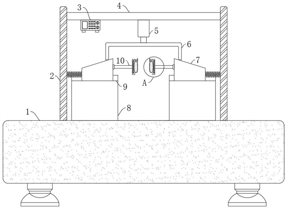
[0025] refer to Figure 1-2 , a cutting workbench for scrap steel recycling, comprising a cutting table 1, two support plates 2 fixedly connected to the upper wall of the cutting table 1, two placement seats 8 fixedly connected to the upper wall of the cutting table 1, two support plates 2 The opposite side walls are jointly fixedly connected with a top plate 4 .

[0026] The upper end of the cutting table 1 is provided with a clamping mechanism for clamping steel materials. The clamping mechanism includes two placement grooves 9 arranged on two placement seats 8, and a moving seat 7 is slidably connected in the two placement grooves 9. The side walls of the mobile seat 7 are elastically connected with the side walls of the support plate 2 by extension springs, and the upper side walls of the two mobile seats 7 are provided with inclined surfaces, and the side walls of the two mobile seats 7 are respectively fitted with the two placement grooves 9 inner walls to ensure The mo...

Embodiment 2

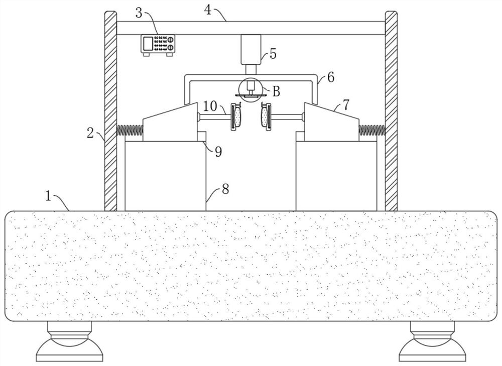
[0031] refer to Figure 3-4 , a cutting workbench for waste steel recycling and processing, the lower side wall of the push rod 6 is fixedly connected with an electric telescopic rod 17, the telescopic end of the electric telescopic rod 17 is fixedly connected with a moving plate 18, and the lower side wall of the moving plate 18 is fixedly connected with a connecting rod. electric board19.

[0032] In embodiment 1, when steel is clamped, two contact plates 16 must be made to contact so that the two electromagnetic plates 12 can be energized to have a better clamping effect. Therefore, embodiment 1 is suitable for clamping more Small or thinner steel, compared with Embodiment 1, in this embodiment, when clamping larger or thicker steel, when the two elastic bladders 13 are deformed to the maximum extent, the two contact pieces 16 still have no Contact each other, at this moment, can start electric telescopic link 17, make electric telescopic link 17 extend, drive mobile plate...


PUM


Abstract

The invention discloses a cutting workbench for waste steel recycling. The cutting workbench comprises a cutting table, two supporting plates are fixedly connected to the upper wall of the cutting table, two containing bases are fixedly connected to the upper wall of the cutting table, and a top plate is fixedly connected to the opposite side walls of the two supporting plates; a clamping mechanism used for clamping steel is arranged at the upper end of the cutting table, the clamping mechanism comprises two containing grooves formed in the two containing bases, movable bases are in sliding connection with the interiors of the two containing grooves, the side walls of the two movable bases are elastically connected with the side walls of the supporting plates through tension springs, fixing rods are fixedly connected to the opposite side walls of the two movable bases, and clamping plates are fixedly connected to the ends, close to each other, of the two fixing rods. The cutting workbench can effectively prevent the steel from shaking and even falling off during cutting, the cutting work is ensured to be smooth, and meanwhile, the safety of workers is ensured.

Description

technical field [0001] The invention relates to the technical field of steel processing equipment, in particular to a cutting workbench for recycling and processing waste steel. Background technique [0002] In real life, many items used in people's daily life are made of steel materials, such as some knives or other construction materials, etc., and in the process of steel product processing, a large amount of scrap steel will be produced. If these Discarding scrap steel will cause a lot of waste. Therefore, it is necessary to recycle these scrap steel, and these scrap steel need to go through certain processing when recycling, and these scrap steel should be cut. [0003] When cutting steel, it is necessary to clamp and fix the steel. The existing scrap steel cutting device can generally only clamp steel with regular shape (circular or square cross-section), and most of the scrap steel The shape of the steel is irregular. When clamping, it is easy to be unstable and cause...

Claims


Application Information

Patent Timeline
Patent Type & Authority Applications(China)
IPC IPC(8): B23D79/00B23Q3/154B23Q5/28
CPCB23D79/00B23Q3/1543B23Q5/28
Inventor 朱文涛
Owner 朱文涛
Features
  • R&D
  • Intellectual Property
  • Life Sciences
  • Materials
  • Tech Scout
  • Unparalleled Data Quality
  • Higher Quality Content
  • 60% Fewer Hallucinations
Learn More