Protective automatic dismounting device for electric vehicle motor

An automatic disassembly and protection technology, applied in the manufacture of motor generators, electromechanical devices, electric vehicles, etc., can solve problems such as damage to the motor, reduce work efficiency, and difficult to control the impact force, so as to avoid damage, improve work efficiency, reduce The effect of work intensity

Inactive Publication Date: 2020-12-11
福州勃楠电子科技有限公司
View PDF0 Cites 2 Cited by
  • Summary
  • Abstract
  • Description
  • Claims
  • Application Information

AI Technical Summary

Problems solved by technology

[0002] The current electric vehicle motor is usually disassembled and repaired manually. During the disassembly process of the motor, due to the high tightness of the motor assembly, if the motor is disassembled directly by impact, it is easy to cause damage to the motor. Usually, it is necessary to manually repair the motor. On the other hand, after knocking the motor, the work intensity of manual disassembly of the motor is still relatively high, and at the same time it is difficult to control the impact force, and it is easy to damage if the force is too high Motor, insufficient strength will reduce work efficiency

Method used


Image

  • Protective automatic dismounting device for electric vehicle motor
  • Protective automatic dismounting device for electric vehicle motor
  • Protective automatic dismounting device for electric vehicle motor

Examples


Embodiment Construction

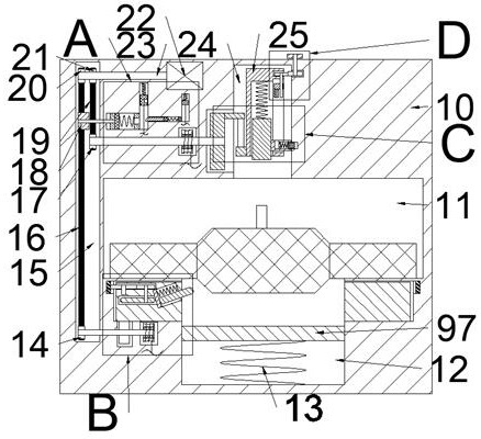
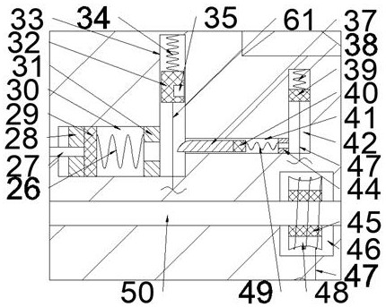
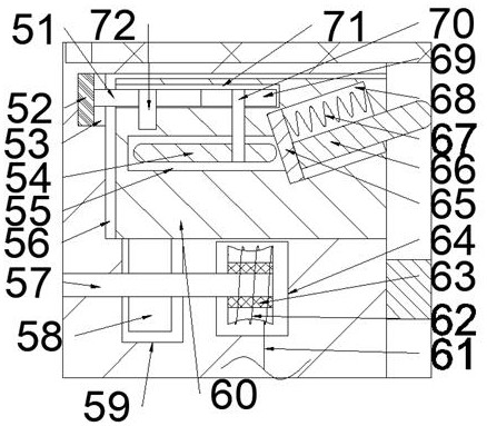
[0018] Combine below Figure 1-5 The present invention is described in detail, wherein, for the convenience of description, the orientations mentioned below are defined as follows: figure 1 The up, down, left, right, front and back directions of the projection relationship itself are the same.

[0019]A protective automatic disassembly device for an electric vehicle motor described in conjunction with accompanying drawings 1-5 includes a main box body 10, and a disassembly cavity 11 with an opening forward is provided inside the main box body 10, and the lower side of the disassembly cavity 11 is A drop chamber 12 is connected to it, and an annular box cavity 56 arranged in a ring is connected to the outer side of the drop cavity 12. The side wall of the annular box cavity 56 is rotatably connected with an annular box 60. On the side wall of the annular box cavity 56 The side end communicates outwardly with an annular ring gear cavity 53, and the lower side of the annular box...


PUM


Abstract

The invention relates to the relevant field of electric vehicle power devices, and discloses a protective automatic dismounting device for an electric vehicle motor. The protective automatic dismounting device for the electric vehicle motor comprises a main box body, wherein a dismounting cavity with a forward opening is formed in the main box body; the lower side of the dismounting cavity communicates with a falling cavity; the outer side of the falling cavity communicates with an annular box body cavity formed in an annular mode; the side wall of the annular box body cavity is connected withan annular box body in a rotating fit manner; the tail end of the upper side of the side wall of the annular box body cavity outwards communicates with an annular inner gear ring cavity; the annularbox body drives a knocking block to rotate, so that uniform knocking at each part of the motor in the circumferential direction is realized; the motor is loosened relative to a hub; and the motor canbe favorably dismounted in the subsequent process; an impact block impacts the upper end surface of a motor main shaft under the effect of an impact spring; dismounting of the motor is realized; and the magnitude of accumulated force of the impact spring is changed by adjusting the position of an impact magnet, and the damage to the motor due to excessive dismounting force is avoided as much as possible.

Description

technical field [0001] The invention relates to the related field of electric vehicle power devices, in particular to a protective automatic disassembly device for electric vehicle motors. Background technique [0002] The current electric vehicle motor is usually disassembled and repaired manually. During the disassembly process of the motor, due to the high tightness of the motor assembly, if the motor is disassembled directly by impact, it is easy to cause damage to the motor. Usually, it is necessary to manually repair the motor. On the other hand, after knocking the motor, the work intensity of manual disassembly of the motor is still relatively high, and at the same time it is difficult to control the impact force, and it is easy to damage if the force is too high Insufficient strength of the motor will reduce work efficiency. Contents of the invention [0003] The object of the present invention is to provide an electric vehicle motor protective automatic disassemb...

Claims


Application Information

Patent Timeline
Patent Type & Authority Applications(China)
IPC IPC(8): B23P19/02H02K15/00
CPCB23P19/02H02K15/00Y02T10/64
Inventor 杨泽玲
Owner 福州勃楠电子科技有限公司
Why Eureka
Try Eureka