Linear sliding block machining jig mechanism

A technology for machining tools and sliders. It is used in metal processing machinery parts, manufacturing tools, metal processing equipment, etc. It can solve the problems of wasted waiting time and other problems, and can simplify complex processing, improve manufacturing capacity, and achieve high linear accuracy. Effect

Active Publication Date: 2020-12-11
陈柏伸
View PDF9 Cites 0 Cited by
  • Summary
  • Abstract
  • Description
  • Claims
  • Application Information

AI Technical Summary

Problems solved by technology

[0007] It can be understood from the above steps that such a manufacturing method must be processed through different machines and equipment; semi-finished products must be continuously loaded and unloaded to change machines for processing, and the manufacturing cost is wasted in the standby time

Method used


Image

  • Linear sliding block machining jig mechanism
  • Linear sliding block machining jig mechanism
  • Linear sliding block machining jig mechanism

Examples


Embodiment Construction

[0074] The technical solutions in the embodiments of the present invention are clearly and completely described below in conjunction with the drawings in the embodiments of the present invention. In the following description, a lot of specific details are set forth in order to fully understand the present invention, but the present invention can also be implemented in other ways different from those described here, and those skilled in the art can do it without departing from the meaning of the present invention. By analogy, the present invention is therefore not limited to the specific examples disclosed below.

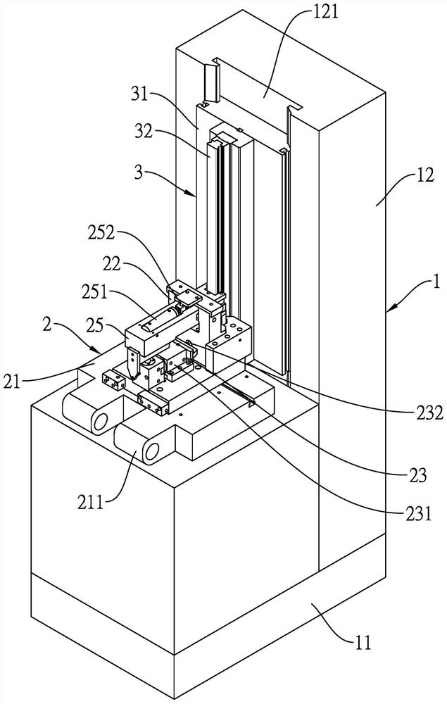
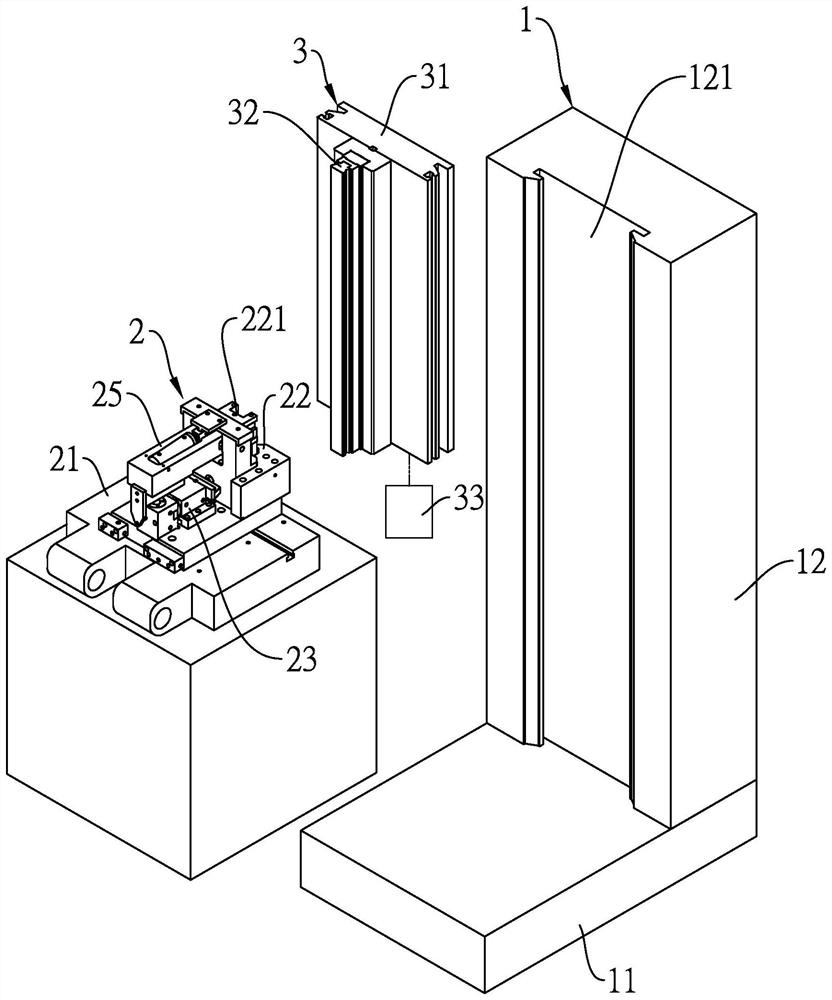
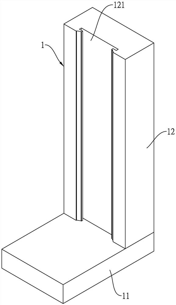
[0075] see Figure 1 to Figure 15 , The linear slider processing jig mechanism of the present invention includes: a machine system 1 , at least one jig processing system 2 , and at least one processing tool module 3 . exist Figure 1 to Figure 9 In the embodiment of the present invention, a set of jig processing systems 2 and a set of processing tool modules 3 are ...


PUM


Abstract

The invention relates to a linear sliding block machining jig mechanism. According to the linear sliding block machining jig mechanism, linear machining equipment is provided with a machining tool anda machining jig, a sliding block is arranged on the machining jig and then machined by the machining tool in the linear direction, and therefore machining of the linear sliding block can be completedthrough the machining jig and the machining tool in different directions, the machining process is simplified, the structural precision of the sliding block can further be improved, and the cost expenditure of a dealer is reduced.

Description

technical field [0001] The invention relates to the technical field of metal processing, in particular to a linear slider processing jig mechanism. Background technique [0002] Linear transmission systems have been used in industrial automation equipment for many years and are very important; common linear transmission systems such as linear guide rail systems, screw transmission systems, linear motion systems and even handling systems are all equipment that use current transmission systems. The part mainly discussed in the present invention is the field of slider manufacturing of the linear transmission system. [0003] The traditional sliders are usually manufactured using two or more kinds of machines and tools. After the blank is formed, the sliders are formed through the following steps: [0004] Step 1: Place the billet on a milling machine to process length; [0005] Step 2: send the semi-finished blank of step 1 to a broaching machine and process it with a broach;...

Claims


Application Information

Patent Timeline
Patent Type & Authority Applications(China)
IPC IPC(8): B23Q1/50B23Q3/00B23Q3/08
CPCB23Q1/50B23Q3/00B23Q3/082
Inventor 陈如潭
Owner 陈柏伸
Why Eureka
Try Eureka