Lifting and cooling liquid heat dissipation device for numerical control machine tool

A technology for heat sinks and CNC machine tools, applied in metal processing machinery parts, maintenance and safety accessories, metal processing equipment, etc. The effect of heat dissipation

Inactive Publication Date: 2020-12-11
东阳宋辰传动科技有限公司
View PDF0 Cites 3 Cited by
  • Summary
  • Abstract
  • Description
  • Claims
  • Application Information

AI Technical Summary

Problems solved by technology

[0002] In traditional small production workshops, often each CNC machine tool cannot get sufficient heat dissipation, and the machine operator will also reduce the operating efficiency due to the overheating of the machine tool while operating the machine tool, and the insufficient heat dissipation of the CNC machine tool will lead to CNC machine tools. The machine tool cannot guarantee the accuracy of the workpiece well when processing the workpiece, which will affect the finished product rate of the workpiece to a certain extent and lead to an increase in the scrap rate of the workpiece. A lifting and cooling liquid cooling device for a numerically controlled machine tool explained in the present invention can solve the problem of above question

Method used


Image

  • Lifting and cooling liquid heat dissipation device for numerical control machine tool
  • Lifting and cooling liquid heat dissipation device for numerical control machine tool
  • Lifting and cooling liquid heat dissipation device for numerical control machine tool

Examples


Embodiment Construction

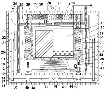
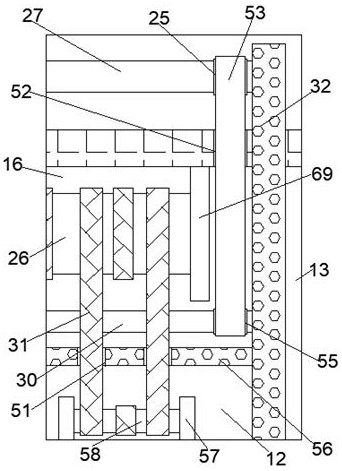
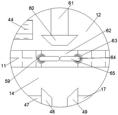
[0017] Combine below Figure 1-5 The present invention is described in detail, wherein, for the convenience of description, the orientations mentioned below are defined as follows: figure 1 The up, down, left, right, front and back directions of the projection relationship itself are the same.

[0018]A lifting and cooling liquid cooling device for a numerically controlled machine tool according to the present invention includes a cooling and cooling box 11, and the cooling and cooling box 11 is provided with a cooling and cooling cavity 12, a fan cavity 13, a driving cavity 14, and a lifting cavity 16. A lifting motor 29 is fixedly connected to the upper end of the cooling heat dissipation box 11. The lifting motor 29 is connected to a lifting drive shaft 27 at one end away from each other. A driven pulley 25 is fixedly connected to the outer peripheral surface of the lifting driving shaft 27. The lower wall of 12 is fixedly connected with an isolated cooling plate 32, the i...


PUM


Abstract

The invention discloses a lifting and cooling liquid heat dissipation device for a numerical control machine tool. The lifting and cooling liquid heat dissipation device comprises a cooling heat dissipation box, wherein a cooling heat dissipation cavity, a fan cavity, a driving cavity and a lifting cavity are formed in the cooling heat dissipation box, the upper end of the cooling heat dissipationbox is fixedly connected with a lifting motor, and the ends, away from the lifting motor are in power connection with lifting driving shafts; a driven belt wheel is fixedly connected to the outer circumferential face of each lifting driving shaft, isolation cooling plates are fixedly connected to the lower wall of the cooling heat dissipation cavity, and the isolation cooling plates isolate the cooling heat dissipation cavity from the fan cavity. According to the lifting and cooling liquid heat dissipation device, after the numerical control machine tool and machine tool operators in a workshop can be lifted as a whole; the numerical control machine tool is cooled, so that it ensured that the use temperature of the numerical control machine tool can reach the optimal use temperature in the machining process, and the precision of a workpiece machined by the machine tool can be ensured; and a large amount of heat is dissipated through rotation of cooling liquid around the machine tool and fan blades, so that the normal use of the operators and the machine tool is ensured.

Description

technical field [0001] The invention relates to the related field of heat dissipation equipment for numerically controlled machine tools, in particular to a lifting and cooling liquid heat dissipation device for numerically controlled machine tools. Background technique [0002] In traditional small production workshops, often each CNC machine tool cannot get sufficient heat dissipation, and the machine operator will also reduce the operating efficiency due to the overheating of the machine tool while operating the machine tool, and the insufficient heat dissipation of the CNC machine tool will lead to CNC machine tools. The machine tool cannot guarantee the accuracy of the workpiece well when processing the workpiece, which will affect the finished product rate of the workpiece to a certain extent and lead to an increase in the scrap rate of the workpiece. A lifting and cooling liquid cooling device for a numerically controlled machine tool explained in the present invention...

Claims


Application Information

Patent Timeline
IPC IPC(8): B23Q11/12B23Q11/00
CPCB23Q11/00B23Q11/126
Inventor 周丽榭
Owner 东阳宋辰传动科技有限公司
Why Eureka
Try Eureka