Metal material surface ultrasonic strengthening treatment device

A metal material and strengthening treatment technology, which is applied in the direction of grinding drive devices, metal processing equipment, grinding/polishing safety devices, etc., can solve the problems of inconvenient cleaning of dust, and achieve the advantages of easy cleaning and collection, saving water resources, and convenient locking Effect

Active Publication Date: 2020-12-11
安徽宏景电镀有限公司
View PDF6 Cites 0 Cited by
  • Summary
  • Abstract
  • Description
  • Claims
  • Application Information

AI Technical Summary

Problems solved by technology

[0010] The purpose of the present invention is to provide a metal material surface ultrasonic strengthening treatment device to solve the problem that the dust settled on the device base is not easy to clean in the above-mentioned background technology

Method used


Image

  • Metal material surface ultrasonic strengthening treatment device
  • Metal material surface ultrasonic strengthening treatment device
  • Metal material surface ultrasonic strengthening treatment device

Examples


Embodiment 1

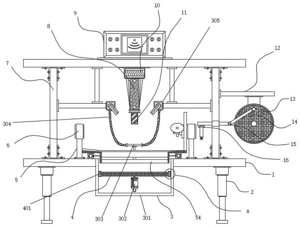
[0038] Example 1: See Figure 1-7 , a metal material surface ultrasonic strengthening treatment device, including a support plate 1 and a foot 2, the four corners of the bottom end of the support plate 1 are fixedly connected with the foot 2, the bottom end of the support plate 1 is provided with a dust-proof mechanism 3, dust-proof The inside of the mechanism 3 is provided with a water-saving structure 4, and both sides of the top of the support plate 1 are fixedly connected with a support column 5, the top of the support column 5 is fixedly connected with a fixing groove 6, and the top of the support plate 1 is fixedly connected with a support frame 7, An ultrasonic generator 9 is fixedly connected to the middle position of the top of the support frame 7, and the bottom end of the ultrasonic generator 9 is provided with an ultrasonic transducer 10, and the bottom end of the ultrasonic transducer 10 is provided with a horn 8, and the horn 8 The bottom end of the tool head 11 ...

Embodiment 2

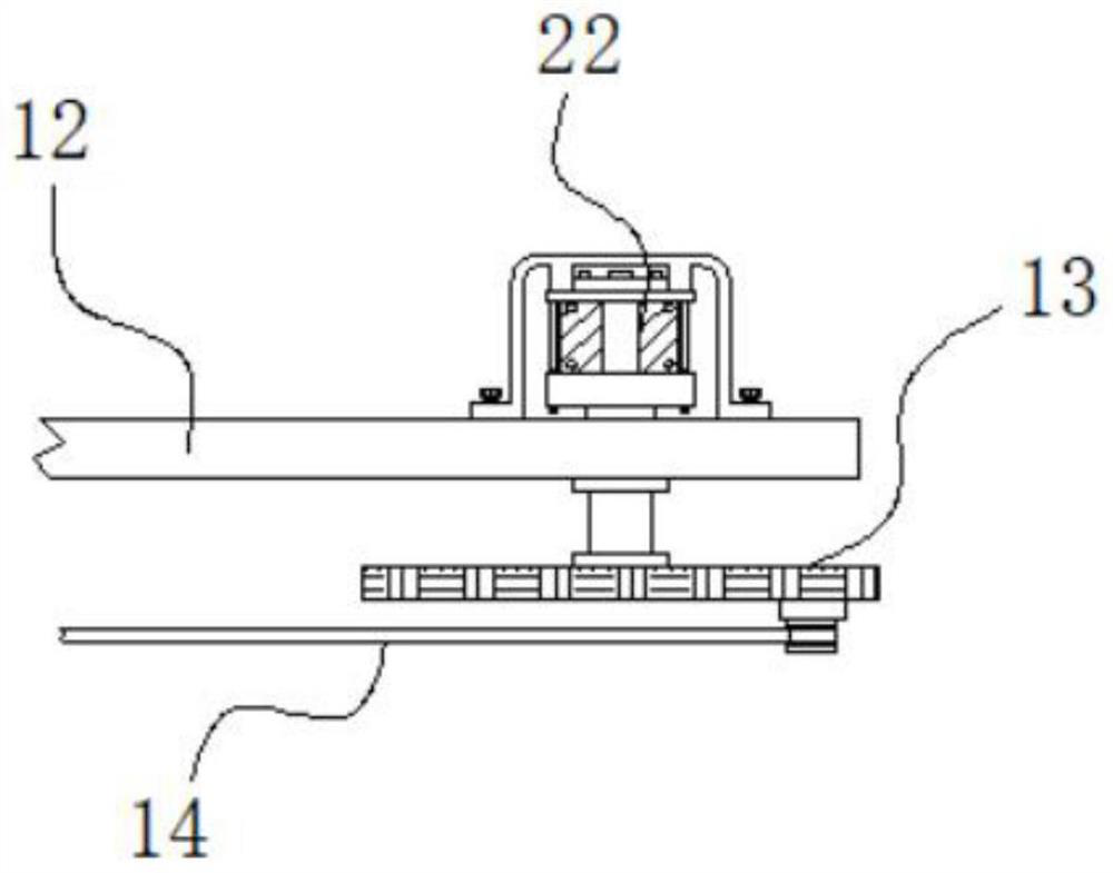
[0042] Embodiment 2: The second driving rod 15 penetrates to the side wall of the support frame 7 and extends to the inside of the support frame 7;

[0043] Specifically, such as figure 1 and image 3 As shown, start the servo motor 22, the servo motor 22 drives the crank 13 to rotate, and the crank 13 will drive the second drive rod 15 to move left and right through the first drive rod 14 during the rotation, thereby driving the metal material to reciprocate, which is convenient for the metal material. The surface is repeatedly processed, and the processing efficiency is high.

[0044] The clamping mechanism includes a connecting seat 16, a first hoop 17, and a second hoop 18. The bottom end on one side of the second driving rod 15 is fixedly connected to the connecting seat 16, and one end of the connecting seat 16 is movably hinged to the first hoop 17. , the other end of the connecting seat 16 is hinged with a second hoop 18, the inside of the first hoop 17 and the secon...

Embodiment 3

[0047] Embodiment 3: The dustproof mechanism 3 is composed of a water tank 301, a water pump 302, a tee pipe 303, a hose 304, a water storage chamber 305, and an atomizing nozzle 306. The water tank 301 is fixedly connected to the bottom end at the middle position of the support plate 1, The lower end of the hopper 54 is located inside the water tank 301. The rear end of the water tank 301 is fixedly connected with a water pump 302. The model of the water pump 302 can be 300QSH. The output end of the water pump 302 is fixedly connected with a tee pipe 303. There is a hose 304, and the water storage chamber 305 is respectively fixedly connected to both sides of the tool head 11, and one side of the water storage chamber 305 is uniformly and fixedly connected to an atomizing nozzle 306;

[0048] The input end of the water pump 302 communicates with the inside of the water tank 301, and the output end of the hose 304 communicates with the inside of the water storage chamber 305; ...


PUM


Abstract

The invention discloses a metal material surface ultrasonic strengthening treatment device, and particularly relates to the technical field of metal surface processing. The metal material surface ultrasonic strengthening treatment device comprises a supporting plate and supporting legs, the supporting legs are fixedly connected to the four corners of the bottom end of the supporting plate, and a dustproof mechanism is arranged at the bottom end of the supporting plate. A rubber wheel is driven to rotate through friction of metal materials in the reciprocating motion process, the rubber wheel is driven to drive a second friction wheel to rotate under the action of friction force in the rotating process, the second friction wheel generates friction to drive a first friction wheel to rotate,and therefore the first friction wheel generates friction to drive a receiving hopper to rotate; and fan blades arranged in the receiving hopper blow airflow to flow downwards, dust is accelerated tomove downwards into the dustproof mechanism, the dust is prevented from diffusing towards the periphery of the receiving hopper, in the rotating process of the receiving hopper, a material stirring rod scrapes the inner side wall of the receiving hopper, the inner side wall of the receiving hopper can be cleaned, and the dust falling into the receiving hopper can be cleaned away and collected conveniently.

Description

technical field [0001] The invention relates to the technical field of metal surface processing, in particular to an ultrasonic strengthening treatment device for the surface of metal materials. Background technique [0002] After the production of metal materials, the outer surface is relatively rough, so the surface needs to be polished to enhance the cleanliness of the surface, so as to facilitate the use of metal materials. In recent years, with the continuous development and progress of science and technology, The surface treatment of metal materials is usually carried out by ultrasonic polishing equipment. The metal surface obtained by ultrasonic polishing is smoother and the processing cost is lower. However, there are still many problems and defects in the existing ultrasonic strengthening treatment devices for the surface of metal materials. [0003] In the process of realizing the present invention, the inventors have found that at least the following problems in t...

Claims


Application Information

Patent Timeline
IPC IPC(8): B24B1/04B24B41/02B24B41/06B24B47/04B24B55/06B24B55/12
CPCB24B1/04B24B55/06B24B47/04B24B41/06B24B41/02B24B55/12
Inventor 常胜宝孟强
Owner 安徽宏景电镀有限公司
Why Eureka
Try Eureka