
Movably-adjustable clamp equipment for piston machining

A technology of activity adjustment and fixture, which is applied in the direction of cleaning method using gas flow, cleaning method and utensils, grinding workpiece support, etc., which can solve the problems of narrow application range, unfavorable work efficiency, inconvenient movement and adjustment position, etc., to improve the application range, avoid dead angles, and improve processing efficiency

Active Publication Date: 2020-12-11
江苏华星机电制造有限公司
View PDF7 Cites 1 Cited by
  • Summary
  • Abstract
  • Description
  • Claims
  • Application Information

AI Technical Summary

Problems solved by technology

[0004] Aiming at the deficiencies of the prior art, the present invention provides a movable and adjustable fixture device for piston processing, which solves the problem that the existing piston cylinder fixture is often fixed with the processing platform in the above-mentioned background technology, which is not easy to move and adjust position, and can only clamp and fix a single-size piston cylinder, resulting in a narrow scope of application, and cannot polish the inside and outside of the cylinder at one time. work efficiency problem

Method used


Image

  • Movably-adjustable clamp equipment for piston machining
  • Movably-adjustable clamp equipment for piston machining
  • Movably-adjustable clamp equipment for piston machining

Examples


Embodiment Construction

[0026] The following will clearly and completely describe the technical solutions in the embodiments of the present invention with reference to the accompanying drawings in the embodiments of the present invention. Obviously, the described embodiments are only some, not all, embodiments of the present invention.

[0027] In the description of the present invention, unless otherwise stated, the meaning of "plurality" is two or more; the terms "upper", "lower", "left", "right", "inner", "outer" , "front end", "rear end", "head", "tail", etc. indicate the orientation or positional relationship based on the orientation or positional relationship shown in the drawings, and are only for the convenience of describing the present invention and simplifying the description, rather than Nothing indicating or implying that a referenced device or element must have a particular orientation, be constructed, and operate in a particular orientation should therefore not be construed as limiting ...

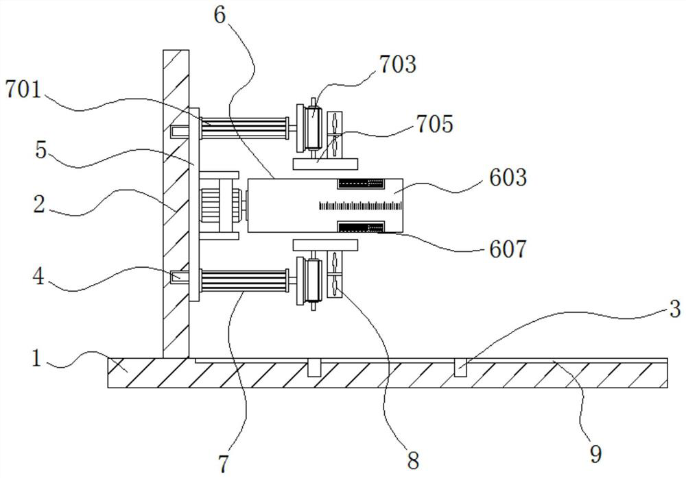
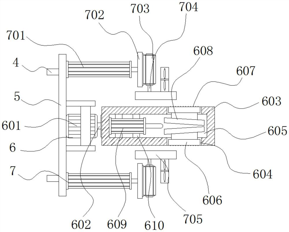
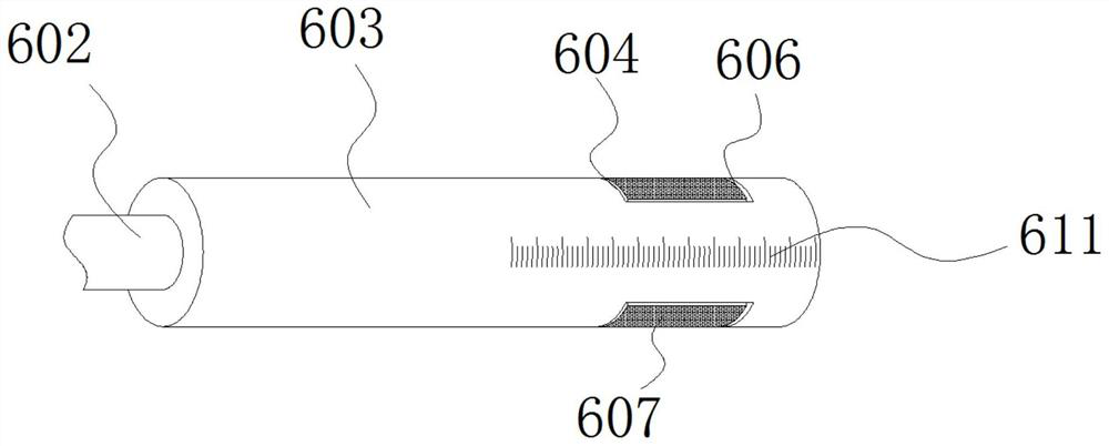

PUM


Abstract

The invention discloses movably-adjustable clamp equipment for piston machining, and relates to the technical field of piston machining clamps. The movably-adjustable clamp equipment specifically comprises a machining platform, an inward clamping mechanism and outward clamping mechanisms, wherein a side platform is welded to one side of the upper surface of the machining platform, and connecting magnetic grooves are formed in the surface of the machining platform and the surface of the side platform correspondingly. and connecting magnetic columns are arranged in the connecting magnetic grooves, the inward clamping mechanism is fixed to the middle of the surface of a clamp base, and the outward clamping mechanisms are distributed at the two sides of the surface of the clamp base. Accordingto the movably-adjustable clamp equipment for piston machining, an inner wall abutting part is lifted out to abut against the inner wall of a piston cylinder body, so that clamping and fixing of thepiston cylinder body are achieved; at the moment, the outer surface of the piston cylinder body is completely exposed, so that a worker can polish the outer surface of the piston cylinder body conveniently; and the bottom of a lifting part is inclined, so that the extending size of the inner wall abutting part is adjusted, piston cylinder bodies of different specifications and sizes can be favorably clamped and fixed, and the application range of the equipment is widened.

Description

technical field [0001] The invention relates to the technical field of piston processing fixtures, in particular to a movable adjustable fixture device for piston processing. Background technique [0002] The piston cylinder is a structural form of the hydraulic cylinder. The input is pressure and flow, and the output is thrust and speed. Its shape is mostly straight or rectangular. In order to prevent the displacement of the cylinder during the grinding process, the piston fixture is an essential and important equipment in the grinding process of the piston cylinder. [0003] The existing piston cylinder clamps are often fixed together with the processing platform, which is inconvenient to move and adjust the position, and can only clamp and fix a single-size piston cylinder body, resulting in a narrow scope of application, and it is impossible to fix the cylinder body at one time. Grinding is performed on the inside and outside, and the fixture needs to be replaced to com...

Claims


Application Information

Patent Timeline
Patent Type & Authority Applications(China)
IPC IPC(8): B24B41/06B03C1/02B08B5/02
CPCB03C1/02B08B5/02B24B41/06
Inventor 王水成
Owner 江苏华星机电制造有限公司
Learn More