Wiring mechanism, wire winding method and wire treatment device and method

A winding method and wire technology, applied in thin material processing, conveyor objects, transportation and packaging, etc., can solve the problems of high cost and low wire processing efficiency, and achieve the advantages of increasing residence time, increasing processing efficiency and reducing costs. Effect

Pending Publication Date: 2020-12-11
NANTONG HUIFENG ELECTRONICS TECH
View PDF9 Cites 1 Cited by
  • Summary
  • Abstract
  • Description
  • Claims
  • Application Information

AI Technical Summary

Problems solved by technology

[0004] Therefore, the technical problem to be solved by the present invention lies in the single-thread transmission of the processing mechanism in the prior art, which leads to the problems of low wire processing efficiency and high cost

Method used


Image

  • Wiring mechanism, wire winding method and wire treatment device and method
  • Wiring mechanism, wire winding method and wire treatment device and method
  • Wiring mechanism, wire winding method and wire treatment device and method

Examples


Embodiment 1

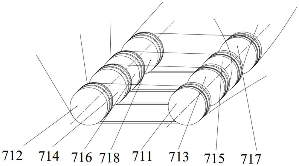
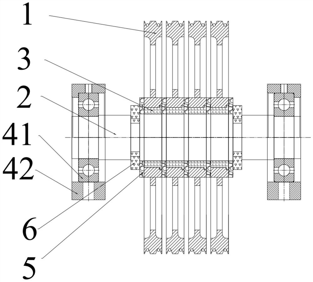
[0052] This embodiment provides a wiring mechanism, such as Figure 1 to Figure 4 As shown, it includes a support 42, a bearing 41, a rotating shaft 2, a shaft sleeve 3, a rotating wheel 1, a spacer 5 and a locking assembly. Wherein, two pairs of parallel bearings 42 are arranged on the mounting position, wherein, the following installation is described with the structure on each pair of bearings 42, specifically, on a pair of bearings 42, the bearings 41 and the rotating Shaft 2 is installed, and four rotating wheels 1 are arranged on each rotating shaft 2, and axle sleeve 3 is also provided between each rotating wheel 1 and rotating shaft 2; In addition, each rotating wheel 1 is provided with two sides The spacer 5 is used to separate adjacent rotating wheels 1 or other components; the locking assembly includes two sets of locking structures 6, and the locking structures 6 are arranged on the outer sides of the rotating wheels 1 on both ends of the coaxial, and the locking s...

Embodiment 2

[0065] This embodiment provides a wire winding method, using the routing mechanism in Embodiment 1, including the following steps:

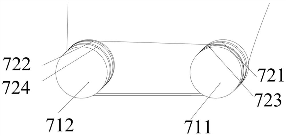
[0066] S11: The first adjacent routing: the wire member first winds clockwise along the first limiting channel of the first rotating wheel, then outputs from the first limiting channel, and goes to the second limiting channel of the second rotating wheel Winding direction clockwise;

[0067] S12: The first cross-wire routing: After the wire member is wound half a turn in the second limiting channel, it is output from the second limiting channel, and extends toward the third limiting channel of the first rotating wheel, and so that the wire member is arranged in the third limiting passage and wound clockwise;

[0068] S13: the second adjacent wiring; the wire member is output from the third limiting channel, and then the wire member extends toward the fourth limiting channel on the second rotating wheel, and the wire member is wound clockwise in ...

Embodiment 3

[0071] In this embodiment, a cable routing mechanism is provided, which is different from Embodiment 1 in that: the first rotating wheel, the third rotating wheel, the fifth rotating wheel and the seventh rotating wheel are arranged on different rotating shafts. The second rotating wheel, the fourth rotating wheel, the sixth rotating wheel and the eighth rotating wheel are arranged on the same rotating shaft. It is also possible to realize the transmission of multiple groups of wire members at different wire speeds.

[0072] Of course, in other optional embodiments, the number of rotating wheels can be set according to the needs of use, for example, three rotating wheels with different rotating shafts can be set, and three rotating wheels with the same rotating shaft can be set for winding Three different wire components.

[0073] When the above wire routing mechanism winds wires, the method adopted can be similar to the method in embodiment 2, as long as the wire members cor...


PUM


Abstract

The invention discloses a wiring mechanism, a wire winding method and a wire treatment device and method. The wiring mechanism comprises at least two rotating wheels which are arranged in a non-coaxial manner, at least one rotating wheel is provided with at least two limiting channels, and any limiting channel is provided with a limiting space for containing and limiting a wire component; and thelimiting channels are arranged on the outer wheel surface in a closed ring shape. According to the wiring device with the above structure, the wire treatment efficiency is improved, the equipment space is reduced, and the cost is saved.

Description

technical field [0001] The invention relates to the technical field of wire surface treatment, in particular to a wire routing mechanism, a wire winding method, a wire processing device and method. Background technique [0002] In the existing electroplating mechanism, by setting two rollers in the surface treatment tank provided with the treatment liquid, the wire member is input from the inlet side of the surface treatment tank, and after bypassing the first roller, then the second roller, Finally, it is output from the outlet side of the surface treatment tank, and the output drive of the wire member is pulled by the driver on the outlet side, so as to realize the electroplating of the wire member. [0003] However, due to the single-thread transmission of the existing processing mechanism, the wire processing efficiency is low and the cost is high. Contents of the invention [0004] Therefore, the technical problem to be solved by the present invention lies in the sin...

Claims


Application Information

Patent Timeline
Patent Type & Authority Applications(China)
IPC IPC(8): B65H51/08B65G49/02B65G39/09B65G39/04B65H51/32B65H57/14B65H57/16C25D7/06C25D17/00
CPCB65H51/08B65H51/32B65H57/14B65H57/16B65G49/02B65G39/04B65G39/09C25D7/0607C25D17/00
Inventor 石明华宋小波陈健蔡成俊
Owner NANTONG HUIFENG ELECTRONICS TECH
Why Eureka
Try Eureka