Cable winding equipment
A cable and equipment technology, applied in the field of cable winding equipment, can solve the problems of not being able to cut in time, inconvenient to take out the cable, etc.
- Summary
- Abstract
- Description
- Claims
- Application Information
AI Technical Summary
Problems solved by technology
Method used
Image
Examples
Embodiment 1
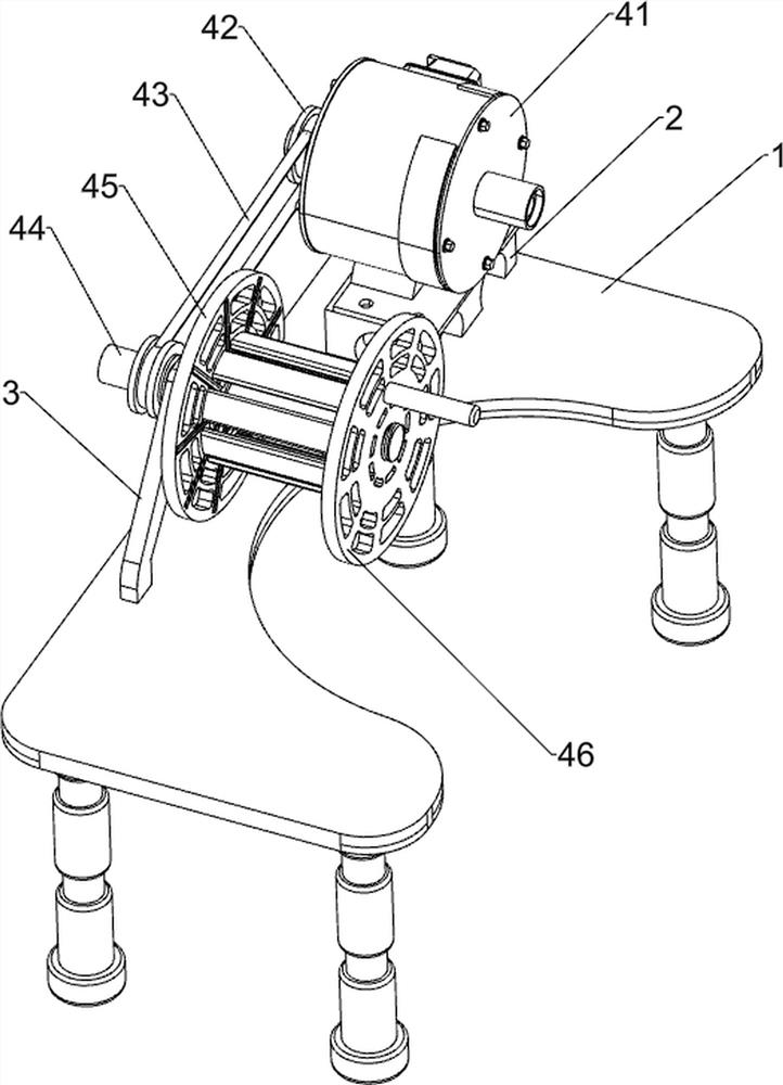
[0023] A cable winding device, such as Figure 1 to Figure 3 As shown, it includes a stand 1, a support 2, a mounting seat 3, a winding mechanism 4, and a moving mechanism 5. The support 2 is connected to the left rear side of the top of the stand 1, and the installation is connected to the middle position of the top of the stand 1. Seat 3, a winding mechanism 4 is connected between the top of the support 2 and the top of the mounting seat 3, and a moving mechanism 5 is connected between the left side of the winding mechanism 4 and the front side of the top of the stand 1.
[0024] The winding mechanism 4 includes a reduction motor 41, the first pulley 42, the first flat belt 43, a rotating shaft 44, a winding wheel 45 and a fixed disk 46, the top of the support 2 is connected with a reduction motor 41, and the top of the mounting base 3 is rotated. Connected with a rotating shaft 44, the output shaft of the decelerating motor 41 and the left side of the rotating shaft 44 are ...
Embodiment 2
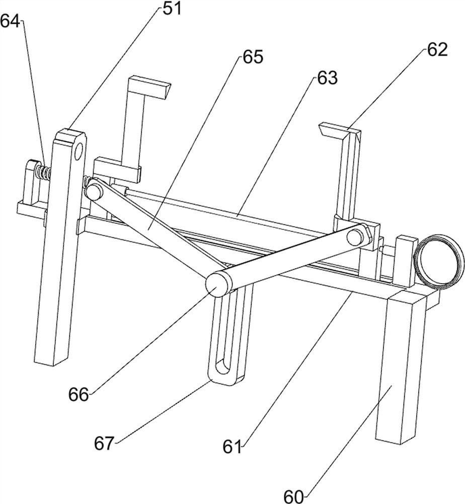
[0028] On the basis of Example 1, such as Figure 4 As shown, a shearing mechanism 6 is also included, and the shearing mechanism 6 includes a fixed block 60, a slide bar 61, an L-shaped blade 62, a pull wire 63, a first spring 64, a connecting rod 65, a round rod 66 and a connecting block 67, The right front side of the top of the stand 1 is connected with a fixed block 60, and a slide bar 61 is connected between the upper part of the fixed block 60 and the rear side of the middle part of the fixed seat 51, and the left and right sides of the top of the slide bar 61 are slidably connected with an L-shaped blade. 62, the front sides of the two L-shaped blades 62 bottoms are all hingedly connected with a connecting rod 65, the middle position of the bottom of the slide bar 61 is connected with a connecting block 67, and the inner side of the connecting block 67 is slidingly connected with a round bar 66, and the round bar 66 The front side of the front side is hingedly connecte...
Embodiment 3
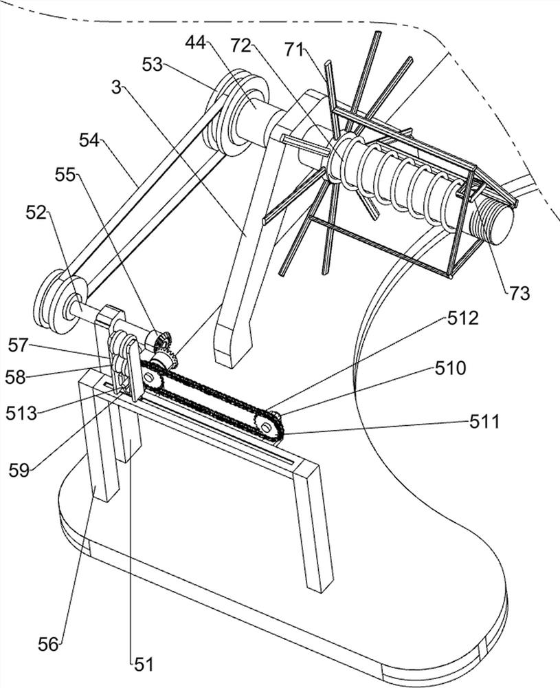
[0031] On the basis of Example 2, such as image 3 with Figure 5 As shown, a push-pull mechanism 7 is also included. The push-pull mechanism 7 includes a push-pull frame 71, a second spring 72 and a handle 73. The rotating shaft 44 is slidably connected to the push-pull frame 71, and the rotating shaft 44 is sleeved with a second spring 72. And the left and right ends of the second spring 72 are respectively connected with the push-pull frame 71 and the reel 45 , the right side of the push-pull frame 71 is slidably connected with a handle 73 , and the handle 73 passes through the right side of the reel 45 .
[0032] When people finish winding and cutting the cable, turn the fixed disk 46 and take it out, then pull the handle 73 to slide to the right, and the second spring 72 shrinks thereupon, and the cable can be moved under the push of the push-pull frame 71. Take it out from the winding wheel 45, when the cable is taken out, release the handle 73, and under the action of ...
PUM
 Abstract
Description
Claims
Application Information
 - R&D
- Intellectual Property
- Life Sciences
- Materials
- Tech Scout
- Unparalleled Data Quality
- Higher Quality Content
- 60% Fewer Hallucinations
Browse by: Latest US Patents, China's latest patents, Technical Efficacy Thesaurus, Application Domain, Technology Topic, Popular Technical Reports.
© 2025 PatSnap. All rights reserved.Legal|Privacy policy|Modern Slavery Act Transparency Statement|Sitemap|About US| Contact US: help@patsnap.com


