
Gate valve

A technology of gate valves and rams, which is applied in the field of pipeline valves, can solve problems such as difficult closing, large operating force, and complex composition, and achieve the effects of reducing opening and closing time, easy opening and closing, and simple structure

Inactive Publication Date: 2020-12-11
黄洪刚
View PDF0 Cites 1 Cited by
  • Summary
  • Abstract
  • Description
  • Claims
  • Application Information

AI Technical Summary

Problems solved by technology

[0003] (1) The valve stem of the prior art gate valve is only subjected to the upward force of the medium in the pipeline. When the pressure in the pipeline is relatively high, the pressure in the pipeline acts on the valve stem, which produces a very large upward force on the valve stem , so that a large operating force is required when the gate is closed, making it difficult to close;
[0004] (2) The gate valve in the prior art drives the valve stem to move up and down through the rotating handle and the screw nut mechanism, so when it is opened and closed, the operating time is longer;
[0005] (3) When the gate valve in the prior art is operated by hydraulic control, it needs to be equipped with a separate oil source or gas source and corresponding control valves externally, which makes the composition more complicated and increases the cost

Method used


Image

  • Gate valve
  • Gate valve
  • Gate valve

Examples


Embodiment Construction

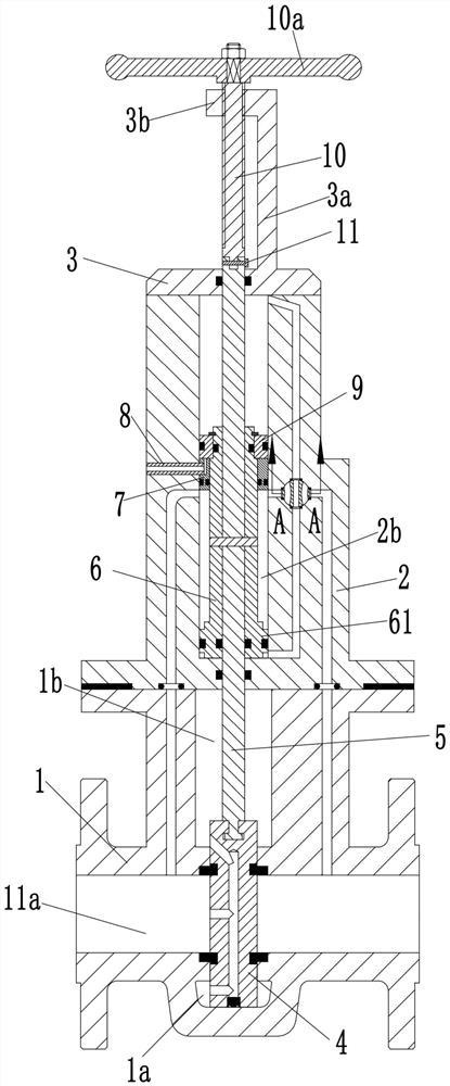
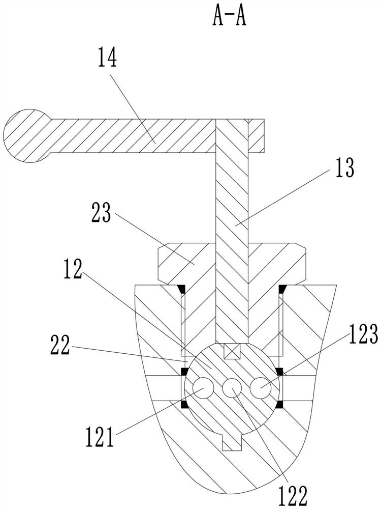
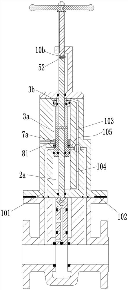
[0024] see Figure 1-5 As shown, a gate valve includes a valve body 1, the valve body 1 is provided with a passage 11a penetrating left and right, the left end of the passage 11a is an inlet, and the right end is an outlet; the inner edge of the valve body 1 is perpendicular to the passage 11a The axial sliding connection of the gate 4 is used to control the on-off of the channel 11a; The upper chamber 1b communicating with the inlet, the valve body 1 is provided with the lower chamber 1a communicating with the inlet at the lower end of the gate plate 4; the upper end of the protrusion 11b is fixedly installed with a valve block 2, and the valve block 2 There is a valve cavity 21 with an upper opening inside, and a cover plate 3 is fixedly installed at the upper opening of the valve cavity 21; The axial sliding connection of the piston rod 6 is connected with the piston rod 6, and the upper end of the piston rod 6 is fixedly installed with an upper piston 9 that is slidably c...


PUM


Abstract

The invention discloses a gate valve which comprises a valve body. A left-right through channel is formed in the valve body; an inlet is formed in the left end of the channel; an outlet is formed in the right end of the channel; a gate plate is slidably connected into the valve body; a bulge is arranged on the outer side of the valve body; a valve block is fixedly installed at the upper end of thebulge; a valve cavity with an opening in the upper end is formed in the valve block; a cover plate is fixedly installed at an opening in the upper end of the valve cavity; a valve sleeve is fixedly installed in the middle of the valve cavity; a piston rod is slidably connected into the valve sleeve; an upper piston is fixedly installed at the upper end of the piston rod; a lower piston is arranged at the lower end of the piston rod; a valve rod with the upper end extending out of the cover plate and the lower end extending into an upper cavity is fixedly installed in the piston rod; the lowerend of the valve rod is connected with the upper end of the gate plate; a first cavity, a second cavity, a third cavity and a fourth cavity are formed in the valve cavity; and a manual assembly and avalve control assembly are arranged at the upper end of the valve block. The gate valve is not only simple in structure and but also capable of being rapidly opened or closed.

Description

technical field [0001] The invention belongs to the technical field of pipeline valves, and in particular relates to a gate valve. Background technique [0002] Gate valve is currently the most important type of valve, which is widely used in the circulation and cut-off of liquid, gas, dust and other media. Usually, the gate valve includes a valve body, the lower part of the valve body has an inlet and an outlet, and the left end of the inlet and the right end of the outlet both have a sealing surface, and a gate plate that can move up and down and not rotate is installed between the two sealing surfaces. . Simultaneously, a valve stem is connected to the top of the flashboard, and a handle is connected to the top of the valve stem through a screw nut mechanism. After the handle is rotated, the screw nut mechanism drives the valve stem to move up and down, and then the shutter moves up and down to seal or open the two sealing surfaces, and finally form the connection or cu...

Claims


Application Information

Patent Timeline
Patent Type & Authority Applications(China)
IPC IPC(8): F16K3/02F16K3/30F16K31/143
CPCF16K3/0254F16K3/30F16K31/143
Inventor 黄洪刚张柏尹肖飞
Owner 黄洪刚
Learn More