Intelligent video monitoring security system

An intelligent video surveillance and security system technology, applied in the multimedia field, can solve the problems that the hole and the video surveillance system cannot be installed precisely, affect the video surveillance range, and the video surveillance system is easy to shake, etc., to ensure the transmission quality, easy to install and fix, Guaranteed effect of stability

Active Publication Date: 2020-12-11
亳州市鑫联宇电子科技有限责任公司
7 Cites 0 Cited by

AI-Extracted Technical Summary

Problems solved by technology

[0003] The holes on the aluminum veneer and the video surveillance system cannot be installed precisely, which causes the video surveillance system installed on the aluminum veneer with holes to shake easily, which affects the stability of the...

Method used

Described adjustment frame group 3 comprises fixed screw rod 31, lap plate 32, adjustment cylinder 33, adjustment plate 34, execution bolt 35, monitoring head 36, ring gear 37, adjustment motor 38 and gear plate 39; The left end of the overlapping plate 32 is installed on the fixed plate 21 through the fixed screw rod 31, and the lower end of the overlapping plate 32 is provided with a mounting groove, and the described adjusting cylinder 33 is symmetrically arranged on the inner wall of the mounting groove of the overlapping plate 32, and the adjusting cylinder 33 The top end of the adjusting plate 34 is connected to the adjusting plate 34, and the adjusting plate 34 is installed in the installation groove of the overlapping plate 32 through a sliding fit; and the side wall of the adjusting plate 34 is provided with a ball and an overlapping plate The side walls of the mounting grooves 32 cooperate with each other; the middle part of the adjustment plate 34 is provided with a guide hole, and the execution bolt 35 passes through the guide hole of the adjustment plate 34 and is installed on the monitoring head 36 through a bearing. The outer wall of the monitoring head 36 is covered with a ring Gear 37, described adjustment motor 38 is installed on the lower end outer wall of adjustment plate 34 by motor base, and the output shaft of adjustment motor 38 is equipped with gear disc 39, and described gear disc 39 and ring gear 37 are mutually meshed; In order to ensure monitoring The quality of picture, adjusts the position of adjusting plate 34 by adjusting cylinder 33, and realizes fine-tuning to monitoring head 36 direction according to regulating motor 38 work; Thereby guarantee the quality transmission of monitoring picture; The direction and position of the camera can be adjusted to ensure the quality of the monitoring picture.
Described clamping module 24 comprises clamping sleeve rod 241, tightening nut 242, clamping block 243, adjustment spring 244 and adjustment stay cord 245; Described clamping sleeve rod 241 left end is installed by flange On the outer wall of the left end of the fixed plate 21, the left end of the clamping sleeve rod 241 is provided with threads, and the left end of the clamping sleeve rod 241 passes through the fixed sleeve rod 11 and is screwed and fixed by the tightening nut 242; the clamping sleeve rod 241 The outer wall is symmetrically provided with a chute that is high on the left and low on the right, and the chute of the clamping sleeve rod 241 is evenly provided with a clamping block 243 through a sliding fit. The bit holes cooperate with each other; the bottom end of the clamping block 243 is provided with movable beads through a movable connection mode, and the movable beads are arranged at the bottom end of the clamping block 243 through a movable connection mode to promote the clamping block 243 in the clamping sleeve rod 241 The sliding ability inside the chute on the top; it is fu...

Abstract

The invention provides an intelligent video monitoring security system which comprises a fixing device, a supporting assembly and an adjusting frame set. One end of the fixing device penetrates through an aluminum veneer curtain wall with a hole; the supporting assembly is mounted in the aluminum veneer curtain wall; the supporting assembly is matched with the outer wall of the aluminum veneer curtain wall with the hole in a propping mode. and the adjusting frame set is installed on the supporting assembly. According to the intelligent video monitoring security system, the problems that a holein an aluminum veneer and a video monitoring system cannot be accurately matched and installed when an existing video monitoring system is installed on the aluminum veneer with the hole, as a result,the video monitoring system installed on the aluminum veneer with the hole is prone to shaking, and the stability of the video monitoring system is affected, the transmission quality of a video monitoring picture is further affected, a video monitoring system installed on the aluminum veneer is inconvenient to adjust, and the monitoring range of the video is influenced are solved.

Application Domain

Technology Topic

Image

  • Intelligent video monitoring security system
  • Intelligent video monitoring security system
  • Intelligent video monitoring security system

Examples

  • Experimental program(1)

Example Embodiment

[0019] Embodiments of the present invention will be described below with reference to the accompanying drawings. During this process, in order to ensure the clarity and convenience of the description, we may exaggerate the width of the lines or the size of the components in the illustrations.
[0020] In addition, the following term is defined based on the function in this invention, and may differ according to a user, an operator's intention, or convention. Therefore, these terms are defined based on the entire content of this specification.
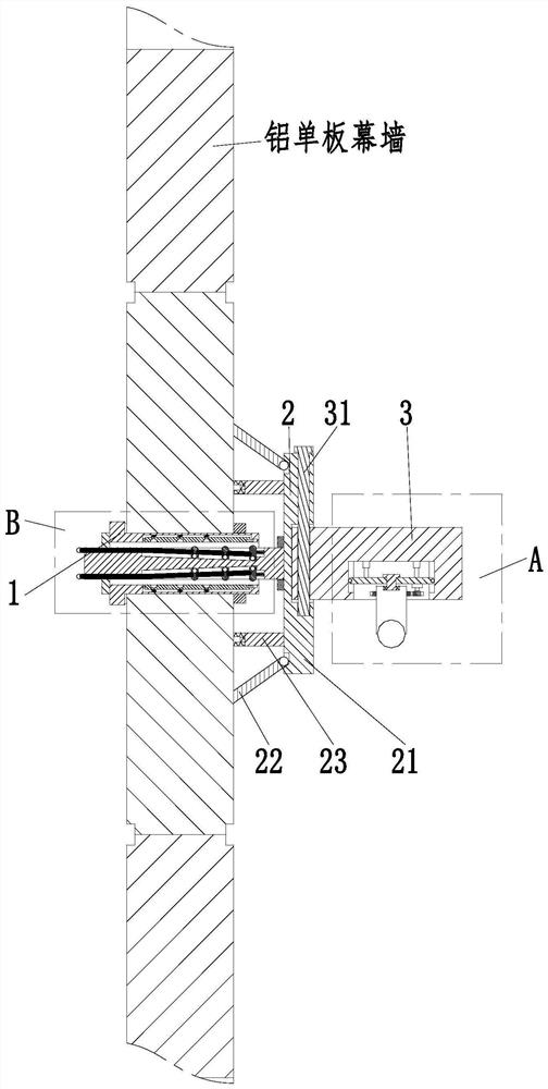
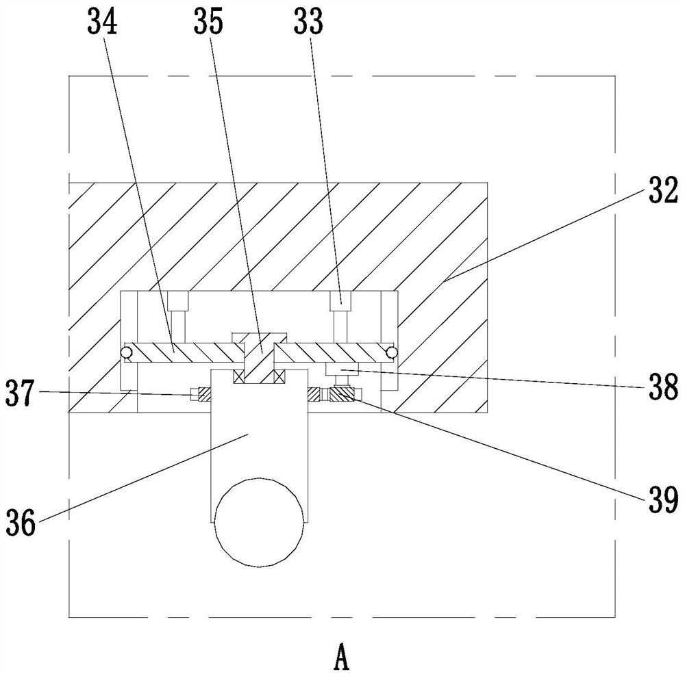
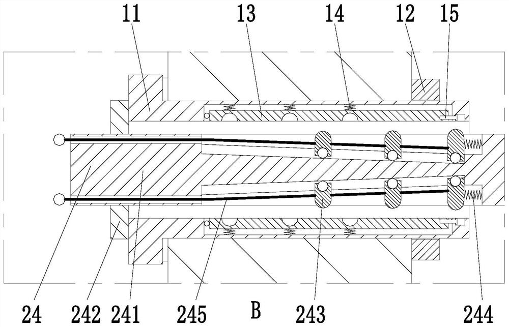
[0021] like Figure 1 to Figure 3 As shown in the figure, an intelligent video surveillance security system includes a fixing device 1, a supporting component 2 and an adjusting frame group 3; one end of the fixing device 1 is installed with a supporting component 2 through the inside of the aluminum veneer curtain wall with holes. The supporting assembly 2 is in conflict with the outer wall of the aluminum veneer curtain wall with holes; an adjusting frame group 3 is installed on the supporting assembly 2; wherein:
[0022] The fixing device 1 includes a fixing sleeve rod 11, a fixing nut 12, a fixing card plate 13, an auxiliary spring 14 and a fixing bolt 15; the fixing sleeve rod 11 is an annular sleeve structure; the outer wall of the fixing sleeve rod 11 is provided with There are threaded grooves; the fixing sleeve rod 11 passes through the aluminum veneer curtain wall with holes, and the outer wall of one end of the fixing sleeve rod 11 is fixed on the aluminum veneer curtain wall by the fixing nut 12, and the interior of the fixing sleeve rod 11 is uniform A card slot is provided, one end of the fixed card plate 13 is installed in the card groove of the fixed sleeve rod 11 through a pin, and the lower end of the fixed card plate 13 is evenly provided with arc-shaped limit holes, and the upper end of the fixed card plate 13 is uniformly arranged The auxiliary spring 14 is connected with the inner wall of the slot of the fixed sleeve rod 11; the fixed latch 15 is installed in the interior of the fixed sleeve rod 11 and is fixedly connected with the right end of the fixed clamp plate 13; the set fixing device 1 passes through the belt The perforated aluminum veneer curtain wall, by cooperating with the holes of the aluminum veneer curtain wall, ensures the stability of the fixing device 1 on the aluminum veneer curtain wall, and facilitates the installation and fixation of the device.
[0023] The support assembly 2 includes a fixed plate 21 , a support column 22 , a limit rod 23 and a clamping module 24 ; the left end outer wall of the fixed plate 21 is symmetrically provided with a support column 22 through a hinged connection, which is located at the left end of the fixed plate 21 . A limit rod 23 is arranged symmetrically up and down the outer wall, and the limit rod 23 is located on the inner side of the support column 22. The top of the limit rod 23 is provided with a rubber pad; the top of the limit rod 23 is provided with a rubber pad to promote The limit rod 23 cooperates with the outer wall of the aluminum veneer curtain wall to improve the friction between the two, ensure its stability, and effectively prevent the outer wall of the aluminum veneer curtain wall from being damaged and scratched by the limit rod 23; the left end of the fixed plate 21 A clamping module 24 is installed at the middle position of the outer wall through the flange.
[0024] The clipping module 24 includes a clipping sleeve rod 241, a tightening nut 242, a clipping block 243, an adjustment spring 244 and an adjustment cable 245; the left end of the clipping sleeve rod 241 is mounted on the fixing plate through a flange 21, the left end of the clamping sleeve rod 241 is provided with threads, and the left end of the clamping sleeve rod 241 passes through the fixing sleeve rod 11 and is screwed and fixed by the tightening nut 242; the outer wall of the clamping sleeve rod 241 is symmetrically arranged There are oblique grooves with left high and right low, and the clamping block 243 is evenly arranged in the inclined groove of the clamping sleeve rod 241 by sliding fit. Matching; the bottom end of the clamping block 243 is provided with movable beads through movable connection, and the bottom end of the clamping block 243 is provided with movable beads through movable connection, which promotes the tilting of the clamping block 243 on the clamping sleeve rod 241 The sliding ability inside the groove is further improved; it is further convenient for the clamping block 243 to be clamped into the arc-shaped limit hole of the fixed clamping plate 13; the adjustment pull rope 245 is passed through the evenly arranged clamping block 243 by the left end of the clamping sleeve rod 241 Make a fixed connection; the outer wall of the clamping block 243 located at the leftmost end of the clamping sleeve rod 241 is connected with the inner wall of the right end of the chute of the clamping sleeve rod 241 through the adjustment spring 244; In order to ensure that the device is fixed with the holes on the aluminum veneer curtain wall, the device can be prevented from shaking and the transmission quality of the monitoring picture can be ensured.
[0025]The adjustment frame group 3 includes a fixed screw 31, a lap plate 32, an adjustment cylinder 33, an adjustment plate 34, an execution bolt 35, a monitoring head 36, a ring gear 37, an adjustment motor 38 and a gear plate 39; the overlapping connection The left end of the plate 32 is mounted on the fixed plate 21 through the fixed screw 31, the lower end of the lap plate 32 is provided with a mounting groove, the adjusting cylinder 33 is symmetrically arranged on the inner wall of the mounting groove of the lap plate 32, and the top end of the adjusting cylinder 33 is connected On the adjustment plate 34, the adjustment plate 34 is installed in the installation groove of the lap plate 32 by sliding fit; and the side wall of the adjustment plate 34 is provided with the installation of the ball and the lap plate 32 through a movable connection. The side walls of the grooves cooperate with each other; the middle of the adjusting plate 34 is provided with a guide hole, and the execution bolt 35 passes through the guide hole of the adjusting plate 34 and is mounted on the monitoring head 36 through a bearing. The outer wall of the monitoring head 36 is sleeved with a ring gear 37, The adjusting motor 38 is installed on the outer wall of the lower end of the adjusting plate 34 through the motor seat, and the output shaft of the adjusting motor 38 is installed with a gear plate 39, and the gear plate 39 and the ring gear 37 are meshed with each other; in order to ensure the quality of the monitoring screen , adjust the position of the adjustment plate 34 by adjusting the cylinder 33, and realize the fine-tuning of the direction of the monitoring head 36 according to the operation of the adjusting motor 38; thus ensuring the quality transmission of the monitoring picture; the set adjustment frame group 3 improves the direction of the monitoring head 36 and The adjustment of the position ensures the quality of the monitoring picture.
[0026] The above descriptions are only preferred embodiments of the present invention, and are not intended to limit the present invention. For those skilled in the art, the present invention may have various modifications and changes. Any modification, equivalent replacement, improvement, etc. made within the spirit and principle of the present invention shall be included within the protection scope of the present invention.

PUM

no PUM

Description & Claims & Application Information

We can also present the details of the Description, Claims and Application information to help users get a comprehensive understanding of the technical details of the patent, such as background art, summary of invention, brief description of drawings, description of embodiments, and other original content. On the other hand, users can also determine the specific scope of protection of the technology through the list of claims; as well as understand the changes in the life cycle of the technology with the presentation of the patent timeline. Login to view more.

Similar technology patents

Fed meat shredding processing device

Owner:安徽靖童科技农业发展有限公司

Multi-lens aerial camera shooting stabilized platform

Owner:GUANGZHOU REDBIRD HELICOPTER REMOTE SENSING TECH

Classification and recommendation of technical efficacy words

  • Guaranteed transmission quality
  • Avoid shaking

Manufacturing method of quartz optical fiber image bundle

ActiveCN102520479AReduce absorption lossGuaranteed transmission qualityGlass making apparatusBundled fibre light guideSkin structureQuartz
Owner:NANJING CHUNHUI SCI & TECH IND

Method for balancing the load of a wireless local area network

InactiveUS7558208B2Guaranteed transmission qualityError preventionTransmission systemsMethod selectionLow load
Owner:INFINEON TECH TAIWAN

Scalable layered coding based multi-path transmission scheme

InactiveCN102364962AEfficient and reliable transmissionGuaranteed transmission qualityTelevision systemsDigital video signal modificationTelecommunicationsMultipath transmission
Owner:NANJING UNIV OF POSTS & TELECOMM
Why Eureka
Try Eureka