A channel measurement device that reduces staff workload based on safe water use

A technology for staff and measuring devices, which is applied in the direction of measuring devices, mechanical measuring devices, and mechanical devices, can solve the problems of reducing the measurement efficiency of staff, threatening the personal safety of staff, and increasing the workload of staff, so as to improve practicality Sexuality, ease of operation, and the effect of protecting personal safety

Active Publication Date: 2021-04-30
宁夏诚建建设工程有限公司
View PDF6 Cites 0 Cited by
  • Summary
  • Abstract
  • Description
  • Claims
  • Application Information

AI Technical Summary

Problems solved by technology

[0007] The purpose of the present invention is to provide a channel measuring device based on safe water utilization to reduce the workload of staff, to solve the above-mentioned background technology. Measuring devices are used on the channel, such as a ruler to measure the width, depth and length of the inclined surface in sequence, and then record the data on the ruler in the data book in sequence. Since the sequential measurement requires the staff to level it repeatedly, thus increasing the The workload of the staff is reduced, and then the measurement efficiency of the staff is reduced. Moreover, when some existing water use channel measurement devices are used, because the channel has a certain depth, the staff needs to go down to the inside of the channel for measurement, so that When the staff climbs up and down the channel, the staff is prone to slip and fall due to mistakes, and most of the channels are constructed of cement or stone slabs, which is likely to pose a threat to the personal safety of the staff

Method used


Image

  • A channel measurement device that reduces staff workload based on safe water use
  • A channel measurement device that reduces staff workload based on safe water use
  • A channel measurement device that reduces staff workload based on safe water use

Examples


Embodiment Construction

[0027] The following will clearly and completely describe the technical solutions in the embodiments of the present invention with reference to the accompanying drawings in the embodiments of the present invention. Obviously, the described embodiments are only some, not all, embodiments of the present invention. Based on the embodiments of the present invention, all other embodiments obtained by persons of ordinary skill in the art without making creative efforts belong to the protection scope of the present invention.

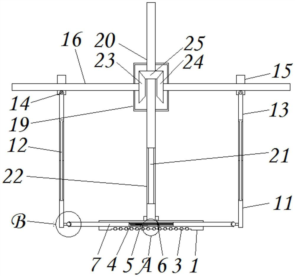
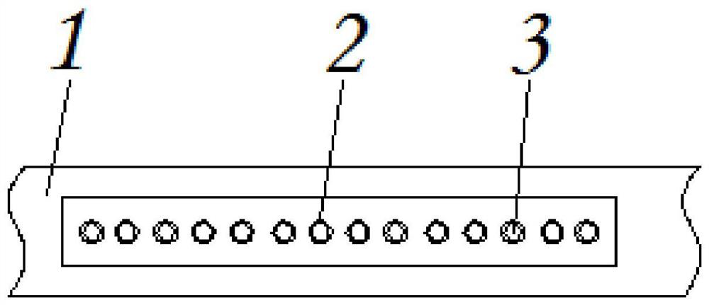
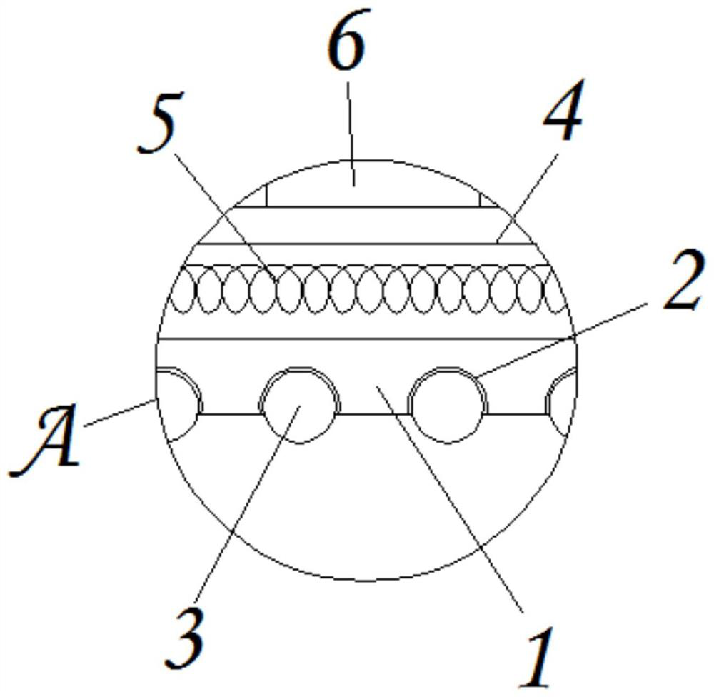
[0028] see Figure 1-7 , the present invention provides a technical solution: a channel measurement device based on safe water utilization to reduce the workload of staff, including a moving seat 1, a receiving groove 2, a moving ball 3, a placement groove 4, a return spring 5, and a rotating block 6 , adjusting rod 7, steering groove 8, steering ball 9, left hypotenuse measuring rod 10, right hypotenuse measuring rod 11, extending measuring rod 12, connecting...


PUM


Abstract

The invention discloses a channel measuring device based on safe water utilization and reducing the workload of staff, which includes a moving seat, an adjusting rod, a left bevel gear and a right bevel gear, and the lower surface of the moving seat is provided with a receiving groove. The left side surface of the steering ball is welded and fixed with a left hypotenuse measuring rod, and the right side surface of the steering ball is welded and fixed with a right hypotenuse measuring rod, and the inside of the right hypotenuse measuring rod is provided with an extension measuring rod, and the extension The outer surface of the measuring rod is provided with a connecting rod, and the upper side of the connecting rod is provided with a support shaft inside, and the end of the support shaft is welded and fixed with a moving block, and the inside of the moving block is provided with a limit rod, and the outer surface of the moving block A placement plate is provided, and a slide groove is opened on the inner surface of the placement plate. The channel measuring device based on safe water utilization and reducing the workload of staff is provided with an adjustment rod, a main shaft rod and a moving block, so that the safety of the staff can be guaranteed during the measurement operation.

Description

technical field [0001] The invention relates to the technical field of water conservancy, in particular to a channel measuring device that reduces the workload of staff based on safe water utilization. Background technique [0002] Water conservancy projects can rationally dispatch water resources, so that water-scarce areas can have sufficient water resources, and water conservancy projects include many, large-scale projects include water-blocking dams, etc., small-scale projects have aqueducts, etc., and aqueducts are under construction Or when renovating, the staff needs to measure the aqueduct, so that they can accurately calculate the amount of building materials such as masonry and cement needed for the aqueduct, so that the budget can be prepared. At this time, a measuring device is needed. [0003] However, some existing water utilization channel measuring devices have the following problems: [0004] 1. It is inconvenient to measure. When some existing measuring de...

Claims


Application Information

Patent Timeline
Patent Type & Authority Patents(China)
IPC IPC(8): G01B5/02G01B5/18
CPCG01B5/02G01B5/18
Inventor 俞彩娣
Owner 宁夏诚建建设工程有限公司
Why Eureka
Try Eureka